Sunday, 14 October 2018

Smart Tank


Historical Background
Even though the Type 90 MBT was still coming off the production line in the 1990s, the Japanese Ground Self-Defense Force decided to update its armoured force to better prepare for 21st-century warfare. After considering buying tanks from abroad (which were too heavy and too large for Japanese terrain) and after assessing the upgrade potential of the Type 90 (and even the earlier, and obsolescent, Type 74), the JGSDF decided that the Type 90 lacked internal space to upgrade their C4I capabilities. Therefore, in 1996, the Technical Research and Development Institute (TRDI) of the Japanese Ministry of Defense began the development of a new tank, under project name TK-X / MBT-X, with Mitsubishi Heavy Industries being appointed to build prototypes. The plan was expected to begin production by 2010-2011 and the prototype made its debut on 13 February 2008 at TRDI's facility in Sagimihara. The Ministry of Defense was impressed with the prototype and a contract was signed in 2010. Following Japanese military tradition, the TK-X/MBT-X was given designation Type 10 after the year of its introduction.

Although the main requirement for the Type 10 seems to be enhancement of C4I capabilities, the initial focus of the project was its weaponry and ammunition. While the Type 90 was armed with a licence-built Rheinmetall 120mm gun, the Type 10 was armed with a 120mm weapon indigenously developed by Japan Steel Works. While it can fire all NATO-standard 120mm rounds, a special Type 10 APFSDS was developed and can only be fired by the Type 10. As with the Type 90, the gun was fitted with a bustle-loaded autoloader, reducing the crew to three. 44-calibres long, the gun can be upgraded to 50- or 55-caliber length. Secondary armament consist of a co-axial Type 74 7.62mm machine gun and a 12.7mm M2HB heavy machine gun which can be remotely controlled from within the turret. The main armour plate is steel but apparently modular applique ceramic and steel composite armour plates is an option according to mission profile and weight requirements.

The Type 10 is lighter than the Type 90 (44 tonnes v. 50 tonnes) allowing the Type 10 to be deployed all around Japan (the Type 90 can only be deployed in Hokkaido as most bridges and roads in the rest of the Home Islands were unable to support the weight of the Type 90). The tank was powered by a water-cooled V-8 diesel engine rated at 1,200 hp. Power was transmitted via CVT gearbox allowing the MBT to move at around 70 km/h. As with its predecessors, the Type 10 was also equipped with a hydropneumatic active suspension allowing it to adjust the ride height, tilt sideways and or adjust the height of the front and rear of the tank. The C4I system can be used to share information among the tanks and also to integrate with the infantry. The advanced systems meant a hefty price tag for the Type 10 (also known as Type 0 Hitomaru) : ¥954 million (US$8.4 million) per vehicle for the initial 13 units and ¥700 million (US$6.5 million) for the rest of the order.

The first delivery of the new tank took place in 2010 and formally entered service in 2012 and current production target was 80 units and could be as high as 600 as older vehicles were retired. In January 2014 the Turkish government expressed in purchasing the Type 10's powerpack for the indigenous  Altay MBT. The deal fell through just three months later, mainly due to Japan's stringent arms export laws.

The Kit
Tamiya was pretty quick off the mark by releasing this kit roughly a year after the real tank entered service. Still conforming to the Tamiya philosophy, the kit comprised of just 205 parts spread among six dark green plastic sprues, two lengths off well-detailed vinyl tracks, a sheet of die-cut clear acetate, a sheet of vinyl mesh plus the usual poly caps and a small decal sheet. The real tank had a smooth exterior with little bumps and bulges usually seen on modern tanks and this also helped in keeping the number of parts low. Simple it may be but existing surface features are very well rendered, except for the tie-downs which are moulded-on., while the vinyl mesh is also a bit of a throwback to the last century.The small decal sheet provide markings for three vehicles:
1. Armored Division, JGSDF Fuji School
2. 2nd Company, 1st Armored School Unit
3. 1st Tank Company, Tank School Unit, Fuji School Brigade

Construction
As the usual practice wth vehicle models, construction started with the lower hull. The suspension arms were installed in the usual way. The idler arm is however quite unique. There were five slots for the 'pimple' on the tab to slide into. Tamiya's instructions have you slot it into the middle, 'neutral' position. The real Type 10 has adjustable suspension so I strongly think that a modeler can replicate his model 'kneeling' by varying the tab's position and by removing the 'pimple' on the suspension arms as needed. I skipped the assembly of the road wheels and went straight to assembling the rear hull panel. The lower hull were set aside at this time and I continue with the upper hull. The front upper hull is a multi-part assembly and I found the fit was not perfect between parts D19 and D22 (but the again, as usual, it could just be me). The provided mesh was cut to act as light guards and I found that it was quite stiff and I resorted to using superglue to bond it to the plastic surface. The clear bits for the episcopes are of semi-cut style (they are of the appropriate width but have to be cut into proper height) and are apparently from Tamiya's earlier Type 90 kit. The side walls and the skirtings were set aside at the moment.

The upper and lower hull hales were then cemented together. There is some gap at the front which was puttied over (the clean-up would be easier if the towing hook are not cemented early on). The lower hull was then painted a base colour of JGSDF Dark Green. I got lazy and painted only the visible areas of the lower hull and the running gears! The tracks were painted Vallejo Anthracite Grey which was then given an AK Interactive Track Wash. Although polystyrene cement can be used on modern Tamiya belt-style tracks, I stick to superglue to get them together. After the tracks were put in place the side skirtings cemented into place and they fit perfectly.

Turret construction started with the gun barrel. It was quite disappointing  because the seam running its length (my bad). I assembled the smoke grenade dischargers in a reverse order from the instructions as I think it was easier that way. The environment sensor at the turret rear is supposed to be moveable after assembly but I find it difficult to handle during the process and end up cementing it in the 'up' poisition. Both the gunner's and commander's sight were finished in closed position. The gun mantlet was assembled and the use of poly caps allow it to remain moveable after assembly. The turret shell consists of multiple parts yet it was easy to assemble without the danger of it askew. At this time I decided to only use the commander's figure so the gunner's hatch is cemented shut. The commander's cupola need some careful assembly as one need to note the location of the locating tabs and in relation, the location for the uh, thingies (upon which the heavy MG is mounted) on the cupola. The turret bustle rack was last. It was quite straightforward work and since the mesh was applied on flat surfaces, its stiffness was not a problem. I however deviated from the instructions by cutting the mesh parallel to the mesh pattern instead of diagonally across it. 

Painting & Decalling
Apparently all Type 10s have similar camouflage patterns and that kind of simply things (in one way). The model was given an overall coat of JGSDF Dark Green (Tamiya XF-73) and was then followed by the camouflage pattern of JGSDF Brown (Tamiya XF-72). The rubber skirting and fenders were painted Tamiya XF-85 Rubber Black while the 'canvas' parts (mantlet cover and spent casing container) were painted XF-49 Khaki. As for markings, I decided not to use the 'school' markings provided with the kit and instead used decals from a little-known Japanese company named Twilight Model. In fact I have never heard of them until they opened a booth at last year's MALCOM. The small-ish sheet provide markings for Type 10s from the 8th and 1st Tank Battalions. Further information were in Japanese characters so there were no further details I can gleaned off. I chose the 8th as their tanks feature a tiger's head insignia which is a bit more colourful than the the 1st Battalion's. The decals were thin and having good register.

Finishing
There aren't much to do at this stage with this kit. The pioneer tools and the tow cable were cemented into place. The model then received the usual wash process. The large stowage basket at the rear were left bare as these tanks have never been seen with stowage (plus I don't have any JGSDF accessories in stock). As they were also fairly new weathering was basically not done save for the usual mud / dust at the lower hull. The dried mud was made by using Aqualine 'Brown Mud' from Wilder Weathering Products while the darker mud was made using Vallejo Dark Mud. The radio aerial stubs were cut and replaced with plastic rods. Only the commander's figure was used and after studying the instructions and photos, I realise that the instructions have the colour callout mixed-up - it has XF-64 Red Brown as the main colour. Anyway, since my brushes aren't fine enough, the flecktarn pattern were not as intricate as it should be...but I think good enough from full-scale 6 feet away!

Conclusion
What else can be expected from a Tamiya kit? The build was straightforward, the details, including the non-slip patches were excellent and great fit all around. Probably the only negative points with the kot is the rather stiff (and having to cut them into shape) mesh for the stowage rack and the two-piece plastic barrel.  

Sunday, 5 August 2018

Cik Mek Su!


Historical Background
In 1969, the Soviets learned of the USAF's F-X program which eventually resulted in the F-15 Eagle. They realised that this new fighter would represent a serious technological advantage over contemporary Soviet fighters. In response, the Soviet General Staff issued a requirement for a Perspektivny Frontovoy Istrabitel (Prospective/Advanced Frontline Fighter). Specifications include a long range, good short-field / austere field performance, excellent agility, heavy armament and speed in excess of Mach 2+. The Central Aerohydrodynamic Instiute (TsAGI) in collaboration with the Sukhoi design Bureau would carry out the aerodynamic design of the new aircraft. The specifications however proved too challenging  and costly for one airframe and in the numbers needed. The specifications were therefore split into two: Lyogyi (light) PFI, which eventually resulted in the MiG-29 and the Tyazholyi (heavy) PFI.

The TPFI was assigned to the Sukhoi OKB which came out as the T-10 which first flew on 20 May 1977. Spotted by Western observers, it was the NATO reporting name 'Flanker-A'. The development program however was bugged with numerous technical problems resulting in a number of crashes and extensive redesigns. Production Su-27 (NATO: Flanker-B) began to enter operational service in June 1985 although problems still persist. It officially entered service in August 1990. Su-27s served with both the Frontal Aviation and Voyska-PVO. Although possesing a good range, the Su-27 still did not have enough range for Voyska-PVO which needed to cover the vast expanse of the Soviet Union. Sukhoi hence developed the Su-27PU, an improved Su-27 capable of serving as a long-range interceptor and as a sort of an airborne command post, supporting the original Su-27, MiG-31 or other manned interceptors of the Voyska-PVO. The two-seat Su-27UB combat trainer was used as the basis as it had the performance of the single-seat Su-27 while two crewmembers were needed for long-range missions. The first Su-27PU flew on 31 December 1989 at Sukhoi's Irkutsk facility.

Known to NATO as the 'Flanker-C', the Su-27PU entered production in 1992. By this time, it was being developed into a multi-role combat aircraft with an eye towards the export market. In 1996, Russian authorities gave it a new designation, the Su-30. The new aircraft was aerodynamically and in general, structurally similar to the Su-27. A combination of low wing loading and powerful basic FBW controls make the Flankers an exceptionally agile aircraft as evidenced by the airshow maneuvers of Pugachev Cobra, tailslide and dynamic decelaration. The use of thrust vectoring exhaust nozzles and canards on some versions of the Su-30 gave even better maneuverability. Although not yet seen in combat trainings, the maneuvers mentioned above have potential combat usage as the rapidly decelerating Su-30 can cause its pursuer to overshoot, as well as breaking the the Doppler radar lock as the relative speed of the Su-30 drops below the radar detection threshold.

The Su-30 is powered by a pair of Saturn (formerly Lyulka) AL-31F low-bypass turbofans, each rated at 28,000 lb thrust. The basic Su-30MK (Modernizirovannyi Kommercehskiy = modernised commercial) is able to fly a 4.5 hour mission at a range of 3,000 km. Inflight refuelling  increases the range to 5,200 km or to a duration of 10 hours. As with the Su-27, the Su-30 is equipped a multi-mode pulse-Doppler radar with track-while-scan and look-down/shoot-down capability. It was also equipped with a OLS-27 IRST system in the nose (offset to the right) allowing an emission-free target detection at a range of 100 km. A single GSh-30-1 30mm cannon (with 150 rounds) forms the fixed armament while external stores can be hung beneath 10 hardpoints. In general, the Su-30 has two distinct versions produced by organisations under the Sukhoi Aviation Corporation. Komsomolsk-on-Amur Aircraft Production Association (KnAAPO) produces the Su-30MKK and MK2 versions tailored for both air-superiority and attack missions and generally similar to the F-15E while Irkut Corporation produces the Su-30MKI and its derivatives. Irkut-designed Su-30s have enhanced features for the air superiority role such as canards, thrust vectoring and long-range phased-array radar.

In 2003, the Royal Malaysian Air Force selected Irkut's Su-30 design to fulfil its requirement for a multi-role combat aircraft. A contract worth US$900 million for 18 aircraft was signed in August that year and the first two Su-30MKM (Modernizirovannyi Kommercheskiy Malaysia) was handed over to RMAF on 24 May 2007. Based on the Indian Air Force Su-30MKI, the MKM has the same engines with thrust vector control and digital FBW system. The MKM however incorporated canards and differs in avionics; Thales of France provided the HUD, NAVFLIR and the Damocles targeting pod. Main sensor is NIIP N011M Bars PESA radar with an aerial search range of 400 km (front) and 60 km (rear). Tracking range is 200 km with up to 15 aerial targets tracked at once and four engaged simultaneously. EW systems are Russian, including KNIRTI SAP-518 jamming pods. The Su-30MKMs are also equipped with South African SAAB Avitronics missile approach warning system (MAWS) and laser warning system (LWS). Weaponry include R-27, R-73 and R-77 air-to-air missiles, Kh-31 anti-ship / anti-radar missiles, Kh-59 Ovod TV-guided stand-off missiles, KAB series laser-guided bombs and FAB series free-fall bombs.

The Kit
Trumpeter first came up with a 1/72 Flanker family when they released the J-11 kit in 2011. This was followed by the release of the Su-27, Su-27UB and this kit in 2012. Apparently reduced in scale from their earlier 1/32 Su-30MKK kit, the 1/72 kit contains 110 parts spread among 13 light grey and 2 clear sprue trees, four decal sheets (one for the weapons, one for cockpit instrument panel faces, one for stencils and essential markings and one for distinctive markings and serial numbers). The parts are well-moulded with nice engraved lines and raised details where appropriate. The canopy and the airbrake are positionable and Sorbitsya ECM pods were provided as an alternative to the wingtip missile launch rails. Weapons fit provided the usual Russian air-to-air weaponry  (4 Archers, 4 IR Alamos, 4 radar-guided Alamos, 4 Adders). The air-to-ground-weapon is however a bit of a disappointment with just a pair of KH-31s (the box art shows a pair of Kh-59 with APK-9 datalink pod in addition to the Kryptons). Decals provide markings for two aircraft although no details were provided as to their identity.

I however intended to finish the model as a RMAF Su-30MKM. While the kit provided some basics (twin-wheel nose gear and the offset IRST ball), other, more significant features would have to be provided by the modeler him/herself. The job seemed too daunting for me and the kit were set aside for months while I tackled other projects. Fortunately, a fellow modeller, Nazaruddin Hashim owner of Naza Model Art, came up with a resin conversion set. The set consists of new LEXs with canards, extended-chord tails, TVC nozzles in 'rest' position and the various bumps and bulges. While the resin parts feature nice engraved and raised lines, there are some air bubbles and imperfections especially on the canards and the tails. Small matter though, just a short session with sandpaper and putty should solve it (the IFF aerials were not included and have to be scratchbuilt by the modeler). For markings I use a decal sheet from Fishbone Inc and the now-defunct VFA Productions.

Construction
I started by washing and cleaning up the conversion parts, removing surface blemish and any mould release agent. Afterwards, I cut out the existing LEX and part of the forward fuselage. The conversion parts follow the base kit's panel lines so knowing where to cut was not a problem especially for the upper fuselage. The lower fuselage however does not have panel lines to follow but the way NMA moulded the replacement LEX makes it easier to mark the areas to be removed. I left the LEX ('shoulders') aside for a while and I turned my attention to the cockpit. The RMAF is very secretive about the interior of its combat airplanes and photos of the interior are very rare. However, a Russian website have the photos of the cockpit during the handing over ceremony for the first two airframes completed and they were used as guides (photos of Indian Su-30MKIs are also useful). The cockpit was painted overall grey ( I'm not sure of the shade so I used Gunze H306. The dashboards are different from the kit decals so I painted (badly!) the MFD screens, cut the instrument decal and place dots of white paint to represent knobs and dials. I however used the kit's side instrument panels.

The fuselage can now be closed, but before that, holes were drilled into the lower half of the wings. While the instructions have you put the exhausts (which have the rear face of the engines moulded on), I really think that they were not needed in this build as the downward angle of the resin TVC blocked the view (not to mention the resin construction themselves). To accommodate the TVCs, the locating lips were removed from the fuselage. The new shoulders were then put in place and needless to say, putty was required to close the gap between the new parts and the fuselage. The canards were however left off at this time. The intake tunnels were next. The solid (with raised framing details) FOD guard were replaced with mesh from my still-unbuilt Tamiya Type 10. It may not look like much but I believe it was way better than the originals (I think it is the best if there is a smaller pitch mesh to represent the actual screen - the larger pitch mesh merely act as the frame). A piece containing the turbine faces was included but I did not attach it as they were quite hidden inside the intake tunnel (it would be totally invisible if the original solid FOD screens were used).

At this time, I decided to leave the tailplanes and ventral fins off to ease painting the unpainted metal areas. The MAWS and LWS antennas were cut from the casting blocks and placed on the model. The conversion kit does not include any instructions as to the placements of these items but there are plenty of photos on the internet for reference. The four LWS bulges came in two sizes : the larger pair went to the sides of the air intakes while the smaller ones went to the front fuselage. The intakes have faint engravings of something (I think it should not be there as MKKs do not have antennas or other electronic 'bumps' in the area) which helps in the placement, more or less. Before supergluing the fins, I deepened the separation line between the rudder and the fin as I think they are too shallow and being too similar with the rest of the panel lines. The fins are not interchangeable - the starboard side has bumps on both sides of the upper half. I tried to drill out the base of the fins for the heat exchanger air intakes but only managed to do so for the port fin (the starboard-side vent is quite small and I don't have a small enough drill bit to drill it out). Thin strips of plastic were cut and positioned on the radome to represent the 'bird slicer' IFF aerials. This was done before radome was cemented to the fuselage to ease handling. The TVC exhaust nozzles were superglued to the fuselage and before I forgot, RWR aerials were cemented to the wing leading edge ( I cut the aerials on the original kit fins and sanded them to size).

Painting and Decalling
I started by painting the radome first, using a mix of Tamiya XF-83 Medium Sea Grey and XF-20 Medium Grey. The unpainted exhaust areas were painted a base of Burnt Iron and the access panels were painted Silver. The front half of the bottom portion look brass-ish in photos, so Mr. Color Silver and Brass were mixed and applied. For the main colour, earlier builds of Su-30MKM models used Medium Sea Grey but a modelling friend suggests that Gunze 337 (FS 35237 Blue Grey) is a closer match. Thinking all paints are created equal (or nearly equal), I used Vallejo 71.114. It looked too bluish and I have to strip it off and used Gunze's version of FS 35237. The leading edge of the fins and the lower half of the ventral fins were painted Medium Sea Grey (Tamiya XF-83) while the dielectric fin caps were painted Medium Gunship Grey (Vallejo 71.097). The nose wheel well is of a yellowish colour which I was not able to pin down so it was simply painted H3317 like the rest of the wells.

As for the markings, I used a mix of decals from Fishbone Inc and VFA Productions and also the kit decals. The Fishbone decals only provide markings for M52-14 with its special tail colour scheme during LIMA 2017 while I wanted to do a line bird. So, the VFA bort and tail numbers were used. I however have to use the Fishbone TUDM roundel (as only they have the 'light blue outside' roundel) even though it has a slight registration problem. A number of Fishbone's stencil decals also have the same registration problems so they were substituted with the kit decals whenever possible. Also some of the decals in the Fishbone sheet were not shown in the instructions so I have to quite constantly refer to photos for the actual placement. At the same time not all of the kit-supplied decals are used on the MKM.So it kind of slowed down the decalling process.

Finishing
As usual, the final stretch started by cementing the landing gears into place. The ventral fins were next. Their tabs however did not fit into the slots, necessitating a cut and basically just butt-jointing them to the fuselage. The various pylons were then cemented to their locations. I decided to use the wingtip ECM pods for my model. They however represent Sorbtsiya, rather than SAP-518 pods used by RMAF. Apparently, the latter has a wider girth than the former (I think). While that can't be helped, the least I can do is to modify the Sorbtsiya pod to look like the SAP-518 by removing and/or relocating details on the pods. As for the weapons loadout, as I have mentioned before, the weapons selection is quite disappointing considering that the real SU-30 is an MRCA. I intended to have my model in SEAD mode with four Kh-31s. As Trumpeter provided only two of the Kryptons, I robbed the other two from my Italeri Su-34. Alas, it was in vain as the Italeri Kryptons were too large. I ended up using the kit Kryptons on the intake pylons, R-77s on the tunnel pylons and two R-27Ts, another pair of R-77s and two R-73s on the wing pylons.

The model then received highlights to the panel lines while the metallic exhaust areas received smoke- and blue-coloured washes to replicate heat staining (or something like that). The more vulnerable parts such as pitot probes and aerials were then cemented. I love having my 1/72 planes having their canopy raised. The kit doesn't allow that so I cut off part of the airbrake raising mechanism, drill a hole at the back of cockpit, stick the cut part and voila! Raised canopy! (Yes it might not be accurate I know). The canards were last and they were superglued in a canted position like can be seen on the real aircraft. 

Conclusion
Previously, modellers wanting to build a Su-30MKM (or for that matter, any canard- and TVC-equipped Su-30) would have to use the earlier Su-27UB kit from Academy plus donor parts from other kits and most often, having to scratchbuild them. The Trumpeter kit allows a basic Su-30 to be made OOB while NMA's conversion kit allows further modification into the MKM version (it can also be made into the basis for any other MKI-type SU-30). While the conversion part (probably in my copy only) suffer from tiny blisters on the surface, it still doesn't detract from the fact it was finely engraved and having a good fit (again, the bad fit which can be seen in the photos are because of my bad trimming on original parts and bad filling and sanding ops afterwards). The base kit is also OK and my criticism are reserved to just the ugly seam on the clear parts and the relative lack of external stores. The Fishbone decal is however quite a letdown with rudimentary placement diagrams and showing only the major decal locations only plus a number of registry problems. Again, my copy is a first-print edition and probably were better for the later editions.


Sunday, 6 May 2018

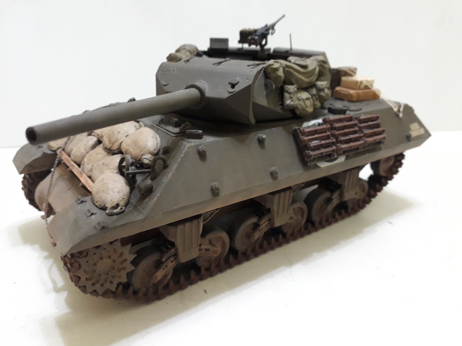
American Panzerjager


Historical Background
In the aftermath of the Battle Of France, the US Army perceived that in the face of the German Blitzkrieg tactics, its units are expected to be faced by large numbers of German tanks attacking on a relatively narrow front. The enemy was expected to break through the thin anti-tank gun screen. Therefore it was decided that the main anti-tank units, the Tank Destroyer battalions should be concentrated and made mobile. This was later turned into the so-called tank destroyer doctrine and was championed by Lt. General Lesley McNair, Commanding General, Army Ground Forces. Under this doctrine, the tank destroyer battalions were to be held as reserve at the corps or army level and to be moved quickly to the site of enemy armoured breakthrough, using aggressive tactics to destroy enemy tanks. This led to a requirement for a fast, heavily-armed vehicle. Although equipped with a turret, the tank destroyer was more heavily gunned, but, in order to be more maneuverable, more lightly armoured than a regular tank, This doctrine was considered to cause the delay in introducing the M26 Pershing heavy tank and limited the Sherman's armament to just 3"/76mm.

The first prototype of a standardised tank destroyer (as there already existed the half-track M3 75mm GMC and the truck-based M6 37mm GMC) was based on the M3 Medium Tank chassis but it was later decided to use the M4 (Sherman) Medium Tank chassis. The first M4-based prototype was designated 3-in Gun Motor Carriage T35. It was armed with a M7 3-in (76.2mm) gun in a circular, open-topped turret (developed from the defunct M6 heavy tank project) and placed on top of a M4A1 chassis. The second prototype, the M35E1 used the M4A2 chassis and used a pentagonal turret with flat, sloped sides, frontal 'beak' and inverted-slope rear face. The turret and the hull plates were held in place by large nuts. In June 1942 it was standardised as the 3-in Gun Motor Carriage M10 and was ordered into production. The M7 gun fired a number of anti-tank rounds including M79 AP, M62 APCBC, M93 HVAP and the APHE. The last mentioned, despite its shortcomings were included in 54 rounds carried. Two large counterweights were carried at the back of the turret because of the weight of the weapon and the lightness of the turret. An M2 .50-cal machine gun, along with 1,000 rounds can be mounted at the top rear of the turret. The weapons were supplemented by the crew's personal weapons for self-protection. Being an M4A2-based vehicle, the M10 was powered by a General Motors 6046 diesel engine rated at 375hp. Later, the M10A1 variant were produced, these differed from the M10 by being based on the M4A3 chassis and used a petrol engine and the last 300 vehicles were armed with a M1 3-in gun with a better performance than the M7.

The M10 first saw action during the final stages of the North African campaign in 1943. The vehicle was successful as it was able to destroy most German tanks in the theatre. The M10 however did not conform to the actual tank destroyer doctrine, and in mid-1944 was supplemented by the smaller and lighter M18 Hellcat. The M10 later faced the Tiger and Panther tanks in Europe, whose frontal armour was proof against the M10, unless a HVAP round was used. In theory, the open-topped turret is a liability in urban or forested areas, making the crew vulnerable to grenades, mortars and artillery. However the turret was liked by the crews as it allow better visibility and communication with the infantry. And should the vehicle be disabled, the open turret allowed them to escape more easily. The doctrine of using armoured vehicles working in close support with the infantry also helped protect them from enemy infantry. Some individual vehicles rigged extra armour to act as a roof, protecting them from mortar and artillery fire. Towards the end of the war, the armour of the M10 was proved to be too thin and was vulnerable to German infantry anti-tank weapons such as the Panzerfaust and the Panzerschreck. To help bolster protection, crews started to pile sandbags on the frontal plate and baulks of timber for the sides. Another weakness was the slow turning rate of the turret - it took 2 minutes to make a full turn, because of manual traverse. However since they operated in larger numbers, and generally being more maneuverable than their opponents, the weakness was not really a distinct disadvantage.

Several hundred M10s were delivered to the Allies as part of Lend-Lease. The British designated their M10s as '3 in Self- Propelled' or 'M10 3 in SP' and was operated by the Royal Artillery. The British M10s saw action in Italy and North-West Europe, many being upgraded with the QF 17-pounder anti-tank gun as the 17pdr SP Achilles. 54 M10s were delivered to the Soviet Union, although there were few records of them in action. The Free French Army also operated M10s, where one M10 named Sirocco, assigned to the Regiment Blinde de Fusiliers Marins, disabled a Panther tank during the liberation of Paris. The Panther was parked near the Arc de Triomphe, with Sirocco at the other end, at the Place de la Concorde. Requiring a snap shot, Sirocco managed to get a first-round hit when the gunner remembered the textbook length of the Champs-Elysses, dialed the range and fired.

A total of 6,706 M10 and M10A1s were built between June 1942 and December 1943. 300 of those were turretless M10A1s designated Full Track Prime Mover M35 used as artillery tractors. Apart from the M18, the M10 was also supplemented by the M36 GMC, armed with a 90-mm gun.

The Kit
Until 1999, the only 1/35 kit of the M10 was the 1960s-vintage Tamiya kit (and its Academy copy). The kit has only basic detailing and is oversized, being more of 1/32 scale. In that year, AFV Club, the Taiwan-based scale model manufacturer released this new-tool kit. The kit consists of 332 plastic parts, 8 vinyl parts (2 track runs and six components for the suspension), 1 nylon string, 1 turned aluminium barrel, 1 spring and a decal sheet. The kit is well-moulded and having good detail, although it, like Tamiya Shermans, has hollow-backed road wheels. Being an open-topped vehicle, AFV Club has included a fairly complete interior, which was way better than the Tamiya kit. No ready rounds are included in the kit and AFV Club suggests a separately available brass ammunition set.  The M10's distinctive applique armour bosses are moulded separately, with tiny raised circles moulded on the hull for their placements. The separate bosses make it easier for modelers to hang goodies on the hull and the turret, without cutting them off first. Grouser racks are also included, together with 26 grousers. The tracks are of the T49 three- bar steel cleat style. AFV Club also suggested the alternative (separately available) workable T51 rubber padded track. Recoiling gun gimmick was included through the use of the supplied spring. Decals provide markings for six vehicles:

1. 'Pistol-Packin' Mama', Tank Destroyer School, Texas 1943
2. 634th Tank Destroyer Battalion, Germany 1944
3. ROC Army, Jinmen Island 1958
4. 'Le-Malin', French 2nd Armored Division, France 1944
5. 'Lion', France 1945
6. 'Essling', France 1945

Construction
Since the M10 is an open-topped vehicle, construction started at the interior. Not much however is included (and as I have never seen the actual interior, it's rather moot actually). What were there however was nicely detailed. There are seats for the driver and his assistant but no control columns were included. The instrument panel was painted and drybrushed (although I shouldn't bother, really). The ammo rack on the sponson is already moulded on but thankfully the tubed rounds are separate, avoiding the ugly moulded-on ammo of Academy's M18. The beautifully-detailed transmission were next. After assembly, it was cemented to the transmission cover and the whole thing was mated to the main hull. The interior then received a rather heavy dark wash. Moving on to the suspension, AFV Club's VVSS suspension has a bit more breakdown than other companies' allowing more articulation especially for dioramas (which I don't need). It was quite tedious but strangely enough, after all the effort making the suspension articulate, they have the wheels with hollow backs.....The rear plate and all the fittings was then fitted to the hull, although I left the exhaust for the time being.

Before doing anything else to the upper hull, the applique armour boss were assembled (they were of two-piece affair) and cemented to the hull. Faint raised circles mark their locations. The driver and co-driver's hatches can be made moveable but I decided to cement them shut as there were no figures to fit there nor there were interior to speak of. The rear plate was then cemented but the tools placed there were left off until after painting has been done. The same goes with the track grouser racks and the track grouser themselves. Before I forgot, the fire extinguisher was painted it was placed on the left hull as per the instructions. Unlike my previous armour builds, the upper hull and the hull pan was not mated prior to painting. Holes were drilled into the transmission cover after which plastic rods were inserted to act as support for timbers used to hold sandbag armour in place. The sandbags were made with two-part putty and while I *think* it looked better than the earlier sandbags on my M13/40 and M5A1 models, there are still plenty of rooms for improvement!

The turret was a multi-piece assembly with separate walls. The details on the walls were cemented first onto the respective walls. AFV Club however did not include the ready rounds and I have to turn to my stash to fill the turret racks - they are however 76 mm rounds instead of 3-inch, so some artistic license was used here, besides, I have no idea of the differences between the two calibres! As mentioned before, AFV Club included the recoil gimmick for the gun but the weight of the metal barrel made the whole assembly quite wobbly so I just superglued the gun in place. The inside of the turret was painted before assembly while the applique armour bosses on the turret walls were left off temporarily while I worked out the stowage

Painting And Decalling
Again, if it's a World War 2-era US vehicle, it will be in Olive Drab. Tamiya XF-62 was the paint used this time while the tyres were painted using XF-63 German Grey. The tracks and grousers were painted a base of XF-64 red brown and given a wash using AK Interactive track wash while the tools (still on their sprues) were painted Steel and Red Brown. The 'timbers' holding the sandbags in place were unpainted and were just given a wash of red brown. As for markings, although the French M10s have colourful insignias, I prefer to have the M10 in its 'native' user's markings and therefore went for a US Army vehicle. I also preferred a front line vehicle and so the first option was out of contention also, leaving the rather bland and boring second option (the majority of M10s have rather boring markings anyway!). The sandbags were painted XF-57 Buff and given a brown wash.

Finishing
The panel lines, engine grille and the armor bosses were given a pin wash. the track grousers were then placed on the hull racks. Note that there aren't enough of the grousers to fill the racks.For accessories, items from Tamiya Allied Vehicle Accessories Set were selected, painted XF-49 Khaki, given a wash and were then cemented to the turret sides - the rolled canvas however needed sanding down (as it was meant to go on a rounded surface, like a Sherman turret perhaps) in order to avoid gaps between it and the turret. There was a slight gap remaining so I slotted a canvas bucket, also from the Tamiya set between the canvas and the turret wall. Other additional items include C-Ration boxes (also from Tamiya), generic boxes from Academy and gas cans from Hero. These were placed on the engine deck. Not much weathering was done, just applying Mig Productions European Dust on the lower hull and tracks.

Conclusion
The AFV Club M10 was considered to be the better of the two M10 kits available at the time I bought my copy. I have not seen the Academy one so I really cannot make a fair comparison. Nevertheless AFV Club kits are bit 'fussier' to build and apparently the shape of the turret is a bit off but to my eyes, it still looks very much like an M10. Nowadays, modellers would probably pick up the new Tamiya kit of the M10 but the AFV Club is still a good alternative. My nitpick with this kit is the lack of rounds for the turret ammo rack and the lack of personal weapons, otherwise it is indeed an excellent kit.

Sunday, 1 April 2018

In The Beginning


I started this hobby with the kit above back in 1983. Being an early 1980s kit and 1/144, the details weren't that awesome with raised panel lines and no cockpit (not even cavity, just blobs of plastic pretending to be the crew's heads). What was truly horrendous was that I glued the parts together using rubber adhesive (the one used by cobblers), the cuts were not cleaned up and my total lack of understanding on the decalling instructions. Instead of the usual dip in water-decal came loose-slide it off the backing paper-apply pressure and dry method, I simply cut the markings, backing paper and all, slather ordinary glue and stick em on their places on the model! Oh, the model was not painted at all. I can't remember whether the kit include landing gears but even if it did, it was not used as it the kit was intended to be more of a toy than a display piece!

Sunday, 25 March 2018

The Other Hellcat


Historical Background
In the aftermath of the Battle Of France, the US Army perceived that in the face of the German Blitzkrieg tactics, its units are expected to be faced by large numbers of German tanks attacking on a relatively narrow front. The enemy was expected to break through the thin anti-tank gun screen. Therefore it was decided that the main anti-tank units, the Tank Destroyer battalions, should be concentrated and made mobile. This was later turned into the so-called tank destroyer doctrine and was championed by Lt. General Lesley McNair, Commanding General, Army Ground Forces. Under this doctrine, the tank destroyer battalions were to be held as reserve at the corps or army level and to be moved quickly to the site of enemy armoured breakthrough, using aggressive tactics to destroy enemy tanks. This led to a requirement for a fast, heavily-armed vehicle. Although equipped with a turret, the tank destroyer was more heavily gunned, but, in order to be more maneuverable, more lightly armoured than a regular tank, This doctrine was considered to cause the delay in introducing the M26 Pershing heavy tank and limited the Sherman's armament to just 3"/76 mm.

The M10 was the first standardised product of this theory but to all intents and purposes it was just an interim vehicle. Back in December 1941, the Ordnance Corps issued a requirement for a fast tank destroyer using the torsion bar suspension, Wright/Continental R-975 engine and 37 mm gun. The requirement for the armament however kept changing, which finally settled on 3"/76 mm as T70 Gun Motor Carriage, standardised in February 1943 as the M18 Hellcat Gun Motor Carriage. The Hellcat was designed by Harley Earl of Buick Motor Company Division of General Motors.  Buick engineers developed an innovative torsion bar suspension that provide a steady ride, even at the road speed of 60 mph (which made the M18 the fastest AFV of World War 2). The Hellcat was subjected to the same tests that were applied to passenger cars at General Motors' Milford Proving Ground. Speed testing was done on paved, banked oval circuit while ride quality was tested on specially developed bumpy stretches. It was also subjected to further tests such as ability to ford six feet of water, climb low walls and ram through structures.

The M18, like other US tank destroyers of the time has an open-top turret which left the crew exposed to the elements, grenades and shrapnel from mortar and artillery. It wasn't really a concern as the maxim 'speed is armor' was applied to the tank destroyer force. In reality however, the high-speed of the Hellcat was rarely applied but when it did, it was used to good effect, allowing flanking moves to be made against the more heavily armoured Panthers and Tigers. The M18 was also designed with simplicity in maintenance in mind, with the engine mounted on rollers which permitted quick removal and maintenance. The transmission could also be easily removed and rolled out onto a front deck plate to facilitate quick inspection and repairs. The M18 was protected by rolled and cast homogenous armour plates,with thickness ranging from 6 mm (floor) to 25 mm (turret front). The main armament was a M1A1 or M1A1C 76 mm gun with 45 rounds (9 ready rounds in the turret). The secondary armament was an M2 12.7 mm machine gun in a ring mount and was provided with 800 rounds.

The M18 first saw combat at Anzio, Italy when T70 prototype was sent there for combat evaluation. Thereafter, the M18 was used on the slog up the Italian Peninsula and later, through the North-West of Europe. The Hellcats were never employed in their intended role per se as the Germans almost never employed their panzers in mass attacks. The TD battalions ended up being distributed among infantry divisions where they provided direct fire support against enemy fortifications or indirect fire against enemy movements. The Hellcat did fought as a pure tank destroyer on many occasions but most notably on 19 September 1944 near Arracourt, France. The 704th Tank Destroyer Battalion was attached to the 4th Armored Division when a platoon from 'C' Company detected a German ambush. The platoon managed to destroy 15 panzers, mostly the feared Panthers for the loss of three M18s. On 19-20 December 1944, during the Battle of The Bulge, the 705th Tank Destroyer Battalion, together with 1st Battalion of the 506th Parachute Infantry Regiment, checked the advance of the 2nd Panzer Division, destroying at least 30 panzers. This is one of the cases where the Hellcat's high speed allowed it to be deployed in a blocking position within a short time. The Hellcat was also used by the Chinese Nationalist Army against the Japanese, but mostly in support of the infantry as Japanese armour in China was comparatively rare.

Post-war, the M18 were sold to other countries. The Republic of China operated some and when the vehicles had worn out, transferred the turret to M42 Duster chassis, turning them into Type 64 light tank. Another user was the former Yugoslavia, using them during the Yugoslav wars of the 1990s. The final user was Venezuela, which still have 75 in reserve. The M18 was produced until October 1944 with 2,507 built. The numbers include the turretless M39 Armored Utility Vehicle.

The Kit
Academy came up with their kit of the Hellcat in 1997. The kit was moulded in dark green plastic and contained 378 parts; the tracks are of single-length vinyl or alternatively, plastic link-and-length type. A length of twine, a small decal sheet and the assembly instructions rounded up the package. Options are provided for guns with or without muzzle brake and also with or without mantlet cover. Despite the year of release, the kit featured slots and holes in the lower hull for motorisation (and that was also perhaps the reason 'static model' was printed on the box top). Being an open-topped vehicle, there were interior details which was adequate in the 1990s. The tracks, both vinyl and plastic. are too thin and are best replaced with aftermarket goodies. Furthermore, I believe there were erroneous parts, especially a round shaped plastic, which I guess is the turret basket floor and the hull floor molded as one. Decals provide markings for two vehicles: 'I Don't Want A', France, September 1944 and 'Dorothy', Germany, December 1944. There are no details about the units those vehicles were assigned to.

Construction
The Academy Hellcat went slightly out of the norm by having you build up the interior first. Having said that, the interior is very basic. There was a partial interior for the drivers compartment with just the driver and assistant driver's seats and a rather nice of representation of the transmission. Bumps (instead of tubes or at least a bit more detailed representations) were moulded on the sponson to represent ammunition stored on that location. The motorisation hole, although out of view, has a blanking plate and it's up to the modeller whether to add the plate or not (I did). The back plate was the cemented to the hull and was then followed by the suspension arms. Several parts, mostly for the two boxes at the rear end of the crew compartment, constitute the interior of the hull. While the suspensions arms were all fitted, the wheels were left off at this time.

The upper hull assembly was rather simple. A few details were cemented underneath the forward area and drivers' hatches were cemented in the closed position (they can be posed in the open position too). The fit between the upper hull and the back plate was not good however - the upper hull should sit flush with the top of the back plate but the slot on the back plate caused the upper hull to sit lower, making the top of the back plate standing proud. I managed to pry off the back plate and after some experimenting, decided to remove the slot and reposition the back plate so that the top stays flush with the upper hull. This however means that the sides near the top are no longer aligned while there were large gaps at the bottom and lower sides, requiring filling for the top and supergluing the bottom and also filling the gaps on the lower sides. While the headlights were fitted, the brush guards were left off at this time as a precautionary measure against rough handling (it's quite ironic, I know). The tools were also left off to ease painting. And speaking of the tools, the kit showed another of its eccentricities : having the tools' locations in faint, raised lines.The skirtings were also left off to facilitate the fitting of the tracks (and further fit problems because of the hull modifications stated above, more on this later..).

If one follows the instructions (like I did), turret assembly started with the assembly of the gun breech. Being the most visible part of the interior, Academy has them pretty detailed (I have seen worse for open-topped vehicle, like the old Italeri M36B1). The breech was the set aside and the turret base was next. While things like turret rotating mechanisms, commander's seat and other stuff were cemented to the base, the gunner's and loader's seats were assembled but also set aside at this time. The turret shell was then cemented together, trapping the trunnion between them. Two types of radios were provided for the turret bustle but no indication which belongs to which markings. The turret ammo rack was then assembled - they include ammunition for a full rack but I somehow think that they are rather anorexic for 76 mm rounds. To ease painting, the breech assembly was pre-painted before being put into place. Academy provided two types of mantlet - one covered and one without cover. I chose the covered mantlet with the appropriate parts for the barrel. Academy also provided plain (M1 gun) and braked muzzle (M1A1C) but again, there was no specific instructions about them. The M2 machine gun was left off at this time.

Painting and Decalling
Generally for WW2 US tanks, you can paint them any colour as long as it was Olive Drab. I used Tamiya XF-62 Olive Drab for this build. The tyres were painted Gunze H77 Tyre Black. The pioneer tools were originally painted the usual colours - steel for the metal parts and Buff/Red Brown for the handles. Although the pioneer tools for US vehicles were actually painted olive drab, but visual interest's sake, I painted the 'wood' parts XF-64 Red Brown and the 'metal' parts in steel. For markings, as I have already used the muzzle-braked gun, I chose the second option, 'Dorothy' as it would be more plausible (according to the rough timeline stated in the instructions). The decals were typically Academy in-house but apply beautifully, perhaps due to the gloss finish. The tracks, including the spare track was painted XF-64 Red Brown and washed with AK Interactive Track Wash. Oh by the way, I chose the belt-style tracks.

Finishing
The painted tracks was looped and being the of old Tamiya style, needed a heated flat screw driver to secure it. The rather ugly connecting area were placed so that it would be hidden by the fenders (despite virtually every photo showing the fenders being removed in the field). And talk about the skirts, the rear pair was affected by the change in the back plate's position. The port side wasn't bad as it only require a little putty to fix the resulting gap. The starboard side was worse as the fender is now further forward than it should be. The brush guards were next and as the cross-beams were divided into two, resulting in misalignment during test-fitting (similar to the light guards in Hobby Boss's ZTZ 96 kit). So I cut the cross beams off, replaced them with styrene rods and touched up the paint. Although the kit provided a sprue from Academy's Allied and German Tank Supplies Set kit, they were not used and I decided to use packs from the Tamiya Allied Vehicles Accessory kits and my spares stash instead. Vallejo Thick Mud was slathered to the lower hull, wheels and tracks.
Conclusion
Apparently the Academy M18 is a hit-and-miss affair and the worse of the two 1/35 M18s in the market. Some reviewers mentioned the gross inaccuracy of the base kit, being dimensioned to fit motorisation (others beg to differ, saying the Academy kit's dimension was not that bad compared to AFV Club's offering) - it still looks like a Hellcat to me . The fit is 50/50 with the worst regarding the rear of the hull and the fit between the gun and the mantlet. Same goes with details - some good, some simplified (to the point of ridiculous like the sponson-stored ammo) and some missing altogether (like the gunner's sight). While the actual M18 tracks looks thinner than its contemporaries, it should not be as (scale) thin as it was in the kit. With just the two companies offering the type in 1/35 they are just the only game in town when it comes to M18s - it's all up to the modeller to choose which one (the Academy was cheaper and that influenced my decision!)