Sunday, 31 August 2014

Flying Tigers' War(t)haw(g)


Historical Background
During the Vietnam War, large numbers of ground attack aircraft were badly damaged, if not shot down by low-level anti-aircraft fire, surface-to-air missiles and even small arms fire, prompting the search for an aircraft able to survive such weapons. In addition, the close-support UH-1 armed Hueys and AH-1 Huey Cobra helicopter gunships were not well-suited for anti-armour operations and the fast jets such as the F-100 Super Sabre, F-4 Phantom II and F-105 Thunderchief were mostly ineffective for close air support because their high speed did not allow pilots enough time to get an accurate fix of targets on the ground, and their thirsty turbojets restricts loiter time. The only effective attack aircraft during the war was the ageing, Korean War-vintage A-1 Skyraider.

In 1966, the USAF formed the Attack, Experimental (A-X) program office and in March 1967, a Request For Information was sent to defence contractors for the A-X. The objective was to create a design study for a low-cost attack aircraft. In 1969, the Secretary of the Air Force asked the aircraft designer, Pierre Sprey to draw up the detailed specifications for the A-X project. Discussions with A-1 pilots and analysis of aircraft then in use for the role indicated that the ideal Close Air Support (CAS) aircraft should have long loiter time, low-speed maneuverability, massive firepower and extreme survivability; or, an aircraft having the best attributes of the Douglas A-1 Skyraider, Henschel Hs 129 and the Ilyushin Il-2. In May 1970, the USAF issued a modified and more detailed Request For Proposals (RFP), taking into account the massive Soviet armoured force and all-weather capability. The RFP specified an aircraft with a maximum speed of 400mph, take-off distance of 4,000 feet, external load of 16,000lb and 460km operational radius. It would also be specifically designed around a 30mm cannon, of which a separate RFP was issued. The RFP for the cannon specified a high muzzle velocity and a rate of fire of 4,000 rounds per minute. Six companies submitted theirs with Northrop and Fairchild Republic selected to build the prototypes : the YA-9A and YA-10A with General Electric and Philco-Ford to build the GAU-8 30mm rotary cannon prototypes. The prototype YA-10A first flew 10 May 1972 and after trials and a fly-off against the YA-9A, was selected on 18 January 1973 for production. The first production aircraft flew in October 1975 and delivery to the USAF commenced in March 1976. The A-10 was officially named Thunderbolt II, as Republic's earlier P-47 Thunderbolt was renowned for CAS missions during World War 2. More popular however is the nickname Warthog, or simply Hog.

The A-10 has superb maneuverability at low speeds and altitude because of its large wing area, high wing aspect ratio and large ailerons. The high wing aspect ratio also allows short take-off and landing capability, permitting operations from primitive airfields near the forward edge of the battle area, or damaged runways. It was also designed to be fueled, rearmed and serviced with minimal equipment. Many of the parts were also interchangeable between either side. The leading edge of the wing, together with the flap shrouds, elevators, rudders and sections of the fins were made using honeycomb panel construction, providing strength with minimal weight penalty. The aircraft was also designed to be tough, being able to survive direct hits from AP and HE projectiles up to 23mm. The flight system is of double redundancy hydraulic type with a mechanical back-up (known as manual reversion system) if the hydraulics were totally lost. The aircraft was also designed to fly with one engine, one tail, one elevator with half of one wing missing. The cockpit and parts of the flight control systems was protected with a 'bathtub' of titanium armour ranging from 13 to 38mm thick; total weight of the 'bathtub' was 540 kg. The two General Electric TF-34-GE-100 turbofan engines were mounted high on the fuselage to decrease Foreign Object Damage risk. The high bypass ratio of the engines means low IR signature and their location, directing the exhaust gases over the tailplane helps mask them further from IR-guided missiles.

The main built-in weapon of the A-10 is the General Electric GAU-8/A Avenger 30mm Gatling-type cannon. One of the most powerful aircraft cannon, the A-10 was designed around this weapon system. The whole gun system weighs 1,828kg with full ammunition load and measures 5.931 m long from the muzzle to the rearmost point of the ammunition system. The magazine can hold 1,174 rounds although 1,150 was the normal load-out. The standard ammunition mix is a five-to-one mix of PGU-14/B Armour Piercing Incendiary rounds, incorporating a Depleted Uranium core, and PGU-13/B High Explosive Incendiary rounds. The rate of fire originally selectable between 2,100 rpm and 4,200 rpm. Later this was fixed at 3,900 rpm. Other weapons include 'dumb' bombs of the Mk.80 family, cluster munitions and laser-guided bombs, although the last mentioned is uncommonly used. A more commonly used guided munitions is the AGM-65 Maverick missile. During Operation Desert Storm the IR camera of the AGM-65D version was used by A-10 pilots as a poor man's FLIR (Forward Looking Infra Red) as the aircraft was not equipped with dedicated FLIR. ECM pods and AIM-9 Sidewinder AAM were also used for self-defence.  

The first unit to receive the A-10 was the 355th Tactical Training Wing based at Davis-Monthan AFB, Arizona. The first mission-capable unit was the 354th Tactical Fighter Wing, then based at Myrtle AFB, South Carolina in 1978. Originally unwelcomed by the fighter community as they traditionally favour speed (not to mention appearance). Furthermore, a number of A-10s were shifted to the role of Forward Air Control (FAC) and designated OA-10. These FAC aircraft however are physically unchanged and remain fully combat capable. The first combat experience for the A-10s came in 1991 during Operation Desert Storm. They flew 8,100 sorties and destroying more than 900 Iraqi tanks, 2,000 other vehicles and 1,200 artillery pieces. They also managed to shot down two helicopters using their cannon while losing four of their numbers to SAMs. Another three battle-damaged aircraft managed to get back to base but were written-off. The Warthog were also active in The Balkans, taking part in Operation Deliberate Force and Operation Allied Force. Although not initially involved, the A-10 was active over Afghanistan during Operation Enduring Freedom and Operation Anaconda. They returned to the Gulf in 2003 during Operation Iraqi Freedom and in 2011 took part in Operation Odyssey Dawn in Libya.

The A-10 has received many upgrades over the years. In 1978, the Pave Penny laser spot tracker was fitted, allowing the aircraft to receive reflected laser radiation from laser designators for faster and more accurate target identification. Inertial Navigation System was received in 1980 and the Low Altitude Safety and Targeting Enhancement (LASTE) upgrade provided computerized weapon-aiming procedure, an autopilot and a ground collision warning system. In 2005 the entire A-10 fleet received Precision Engagement upgrades that include an improved fire-control system, ECM and smart bomb targeting with the aircraft receiving the upgrade designated A-10C (A-10B was a one-off night/adverse weather prototype). The Hog's service may be extended to 2028 although there are proposals for earlier retirement.

The Kit
Italeri released a new tool 1/72 scale A-10A in 1997; this was followed in 1998 by the OA-10A. Although I have not personally checked the original A-10A release, I believe the contents of the boxes are the same. After all, physically, the OA-10A is the same with the A-10A. On initial inspection, it looks like Italeri has a winner here. The panel lines are tiny and crisp, the shape and dimension are generally spot on (although some modelers beg to differ). The cockpit, although paled in comparison with aftermarket resin ones, should look good once painted and weathered with one of the best ACES II ejection seat in plastic that I have ever seen. What truly sets it apart from the Hasegawa kit is the ordnance load - Hydra rocket pods, Rockeye CBUs, Maverick ASMs, Sidewinder AAMs and even a large external fuel tank. The gun barrel however need some work, or help from an aftermarket set. The boarding ladder can be posed in the open position and so are the canopy and the ailerons/speedbrakes. The marking options are for two FS36320/36375-painted aircraft; however Italeri marked the darker colour as FS35257. While already a boring scheme, it was further worsened by the choice of decals - both featured rather anonymous aircraft:
1. 81-962, 52nd Fighter Wing, Spangdahlem; and
2. 80-258, 110th Fighter Group, Michigan ANG, Kellogg ANGB, Battle Creek, Mich.

Construction
As usual with aircraft models, construction started at the cockpit. As mentioned before, the cockpit is actually good enough out-of-the box as it featured detailed and crisp raised details. The cockpit parts and the fuselage sidewalls were painted Gunze Sangyo Aqueous H317 (FS 36231 Dark Gull Grey), XF-1 Flat Black and XF-2 Flat White where appropriate. The ACES II ejection seat consists of  three parts and has good enough detail that I decided not to use a Neomega resin ACES II seat in my stash, saving it for a more needy kit. The bottom half of the forward fuselage, incorporating the nose wheel well was also assembled, after painting the wheel well XF-2 Flat White. Before the fuselage halves were cemented together, Italeri suggested that 30g of ballast should be placed in the nose area. I ended up filling the whole nose cavity with plasticene and I guess it might weigh more than 30g. The fuselage halves did not align well, but the bottom of the nose/nosewheel assembly was more problematic, needing puttying and sanding in order to get the nosewheel assembly to fit to the fuselage halves. Bypassing the assembly of the wings, I assembled the engine nacelles. According to some modelers, the fan blade count for the Italeri A-10 was wrong...I weren't terribly concerned anyway but the fit is, well, bad. None of the engine nacelle parts fit well and require filling and sanding (and I end up forgetting to sand some of the seams!) . Thankfully the entire engine assembly fit nicely with the fuselage and so did the tail assembly.

Then I turned to the wings. Again, like the the fuselage and the engine nacelles, the fit was bad. The upper and lower wing halves have slight misalignment and rather large gaps at the the joint near the wingtips. Thankfully, the latter was at the bottom of the wing so was not really noticeable. The inboard slats was glued in the deployed position (upon reflection, I should have cut the posts and put them in the lowered position). All the pylons were cemented but I leave the Sidewinder and Maverick launch rails for later The same goes with the airbrakes. Returning to the fuselage, I cemented the nosecap and the cannon barrel. The latter has poor detail and I think best enhanced using aftermarket products, Then it is time to paint.

Painting and Finishing
Post-1990s, the colour of the A-10 fleet was rather boring. Apart from a few airframes painted in experimental paint schemes, the rest of the Hogs were painted two-tone greys : Light Ghost Grey FS 36375 and Dark Ghost Grey FS 36320. Rather than using the kit decals however, I used TwoBobs' "Shark Bait" decal sheet, featuring three aircraft from the 74th and 75th Fighter Squadron, 23rd Fighter Group during Operation Iraqi Freedom. The painting scheme is the same with all other Hogs and I used Gunze Sangyo Aqueous paints. For the false canopy underneath the nose, I painted it FS 36118 freehand...yeah, I should have made the masking for it, but laziness had struck me; besides, it was underneath the plane, so it was most likely out of view and I have no intention to enter my models for any competition! The gun barrel was painted XF-1 Flat Black and later on graphite powder was rubbed onto it.

The Twobobs decal sheet featured three aircraft : callsign 'KC', 'Virga' and 'Tweeder'. After reading the background information, I chose 'KC' for my Hog (plus it was the most vibrant). KC or 'Killer Chick' was the call-sign of Captain (now LTC) Kim Nichole Reed-Campbell of the 74th FS, 23rd FG. On 7 August 2003, while flying A-10A s/n 81-987, she took heavy anti-aircraft fire damage over Baghdad while supporting the troops on the ground. The aircraft lost all hydraulics and started to roll left towards the ground. She tried several procedures to get the aircraft back under control; none of which worked. She eventually put the aircraft in the aforementioned manual reversion mode, after which the aircraft responded well. Landing was tricky however, as without hydraulics, there were no airbrakes, brakes and steering. After landing, it was found that the aircraft had suffered damage to the engine and the hydraulic system. Hundreds of holes peppered the airframe and large sections of the aileron were missing. For this action, Cpt. Campbell was awarded the Distinguished Flying Cross.

The Twobobs decals are nicely thin and have good register. The Flying Tiger insignia and the Air Combat Command shield decals have separate white backings to ensure no colour bleed-through. However I still use the kit decals for the IFR probe as it looked like they are nicer than the Twobobs' offering. All the decals responded well to decal softening solutions. The model was then subjected to a combination of sludge wash and 2B pencil for enhancing the details.

Finishing
The final assembly started with the landing gear parts. They are assembled, painted Tamiya XF-2 Flat White and weathered, this time with a thin application of Tamiya X-19 Smoke. Like the rest of the kit, they have nice details and suitably 'pop up' with the wash. I did however lost one part of the main landing gear doors to the Carpet Monster....anyway, unlike many other kits, there weren't many aerials to fit onto the aircraft, as they were already moulded in-situ (and thankfully, they are rather large and quite able to withstand the odd knockings). For the weapons, the TwoBobs instruction sheet includes an arming suggestion, based on a typical A-10 load for CAS missions during Operation Iraqi Freedom:
(Port-to-Starboard)
Station 1: AIM-9M Sidewinder on twin rail launcher
Station 2: LAU-68 7-tube rocket launcher pod
Station 3: AGM-65 Maverick
Station 4-8 : Mk 82 500-lb bomb (Station 5 empty)
Station 9: AGM-65 Maverick
Station 10: LAU-68 7-tube rocket launcher pod
Station 11: AN/ALQ-184 ECM pod (long)

I used the kit's Sidewinders as I have run out of the 'L' (the 'M' has the same physical shape) version in my stash. While the missiles are OK, the twin launcher looks too wide. I tried to use Hasegawa's twin launchers but the one in the Air-To-Air Weapons Set are for the Phantom, furthermore, while dimensionally correct (I guess), the shape was wrong for the A-10's launcher rail. The LAU-68s were also from the kit as Hasegawa's weapon set only have the LAU-3 and LAU-10 pods. The Mavericks are also from the kit, as Italeri moulded the seeker head separately using clear styrene. The Mk.82s came from Hasegawa's Weapon Set I and the ECM pod is from Hasegawa's Weapon Set VII. The AN/ALQ-184 pod however is of the 'short' version. As mentioned before, the airbrakes can be posed in the opened position. In reality however, the airbrakes are hardly left in that position on the ground unless for maintenance. The kit airbrakes however are meant to be in that position only as the instructions did not show the steps to assemble them in the closed position. I tried anyway by simply dry-fitting the halves....they didn't fit well at all. I then tried swapping the lower halves and they have better fit. The fit of the airbrakes to the wing however left a lot to be desired though. I am tired of the kit by this time and left them as they were. Finally, the canopy was fitted in the open position.

Conclusion
Is Italeri's 1/72 Warthog a nice kit? Yes I believe so, with good detail overall. However, the assembly was far from easy, and I ended up having seam lines at the badly-fitting parts (especially at the engine nacelles and the spine of the aircraft); definitely my worst work. As an excuse (ha!), this build actually took place several years ago, when I was at my (extended) Padawan stage and given a second chance, I believe I can make better model out of Italeri's 1/72 A-10s.

Monday, 18 August 2014

World Famous Flying Tigers

Historical Background
Curtiss' P-40 (Hawk 81) was developed from their earlier P-36 Hawk (Hawk 75). In fact the first prototype XP-40 was the 10th production P-36 with the original Pratt & Whitney R-1830 Twin Wasp air-cooled radial engine being replaced with a liquid-cooled, supercharged Allison V-1710 V-12 inline engine and was first flown in October 1938. The original prototype had the coolant radiator placed in the underbelly of the plane, just aft of the wing trailing edge. This however caused a large drag. Curtiss engineers, using data obtained from the National Advisory Committee for Aeronautics (NACA), moved the radiator to the chin position with the air scoop also incorporating the intake for the oil cooler. Improvements to the landing gear fairings and exhaust manifolds also improved the performance and further tests in December 1939 proved that the aircraft could reach 366 mph ( the original prototype can only flew at around 315mph). The Allison V-1710 engine produced around 1,040hp at sea level and at 4,300m, pretty average by the standards of the time and the single-stage supercharger means that it cannot compete with contemporary fighters such as the Bf 109 and was considered unsuitable for the Northwest European Theatre. Consequently, climb performance was also poor for the early P-40s. Later variants which have a more powerful version of the V-1710 engine did however have better capability. However dive acceleration and speed was good, which, in combat, allowed the P-40s to escape the weaker Japanese fighters by simply diving away.

The early P-40s were armed with two 12.7mm M2 machine guns in the nose and two 7.62mm Browning machine guns in each wing. This was later modified to four (and later still, six) 12.7mm M2 machineguns in the wings. The wings are strong, being built from a five-spar structure allowing survival from medium-calibre flak damage and ramming (accidentally or otherwise). Operational range was also superior to the Spitfire and Bf 109 although still short of the Japanese A6M and Ki-43 and Lockheed's P-38. In the Mediterranean and North African theatre, it was considered roughly equal, if not slightly superior, to the Bf 109 and clearly superior against the Italian Fiat G.50 Freccia and Macchi MC.200 Saetta. Against the nimble Japanese fighters, the P-40 cannot match them in a low speed turning dogfight and are best utilised in the 'boom and zoom' tactics, using their superior dive speed, excellent rate of roll and sturdiness. All versions of the P-40 was given the name Warhawk by the USAAC while the British called the early (versions B to C) P-40s as the Tomahawk and the D version onwards as the Kittyhawk.

The early versions of the P-40 can be distinguished from the later versions by having two guns in the nose, with a smaller engine cowling. It was used by the USAAF in defending Pearl Harbor and The Philippines, many being destroyed on the ground. It was also used by the British Desert Air Force in North Africa and Soviet Voyenno-Vosdushnye Sily (VVS) on the Eastern Front. But arguably, the most famous operator of the the P-40, especially the early versions, was the 1st American Volunteer Group (AVG) of the Chinese Air Force, nicknamed The Flying Tigers. The main architect and leader of this group was Colonel Claire Lee Chennault, a former USAAC officer who had worked in China since 1937. Since the United States was not at war with Japan prior to Pearl Harbor, an unpublished Executive Order was signed by President Roosevelt on 15 April 1941 authorising the establishment of an American fighting force within the Chinese Air Force. Pilots, ground crew and administrative personnel were drawn from the USAAC, USN, USMC and some private citizens. Their P-40s were taken from a batch of British orders, convincing the latter to take a later batch of more advanced P-40 variants. The AVG consisted of three squadrons: 1st ('Adam and Eve'), 2nd ('Panda Bears') and 3rd ('Hell's Angels').The P-40s were painted with a shark face on the front of the fuselage, after one of the AVG pilots, Erik Shilling, saw a photograph of a Bf 110 of Zerstorergeschwader 76 in a British magazine. He chalked up a drawing of the shark face on his P-40 to see how it might look and asked for Chennault's permission to use it as his squadron's (3rd Pursuit Squadron) insignia. Chennault instead approved it for use by the whole group, thus cementing the connection between the Flying Tigers and the shark face motif forever.   

The AVG first saw combat on 23 December 1941 when it defended Rangoon, Burma together with Brewster Buffalos of the RAF. The AVG remained in Burma until 27 February 1942 when it pulled back to China, where continued to fight against the Japanese until disbanded and absorbed into the USAAF as the 23rd Fighter Group in Spring 1942. Throughout their existence, the AVG was credited with 229 air-to-air kills, while having 14 pilots KIA, captured or missing. The AVG had better kill/loss ratio than contemporary Allied units mainly due to the use of 'boom-and-zoom' tactics against the more nimble Japanese fighters and also the general obsolescence of the main Japanese fighter at the theatre, the Nakajima Ki-27 'Nate'. In various guises the Flying Tigers survive to this day as the 23rd Wing of the USAF, flying Fairchild Republic A/OA-10 Thunderbolt II attack aircraft and HH-60G Pave Hawk CSAR helicopter and Lockheed HC-130P Combat King CSAR command aircraft.

The Kit
Academy's P-40C kit, released in 2000 is actually a rebox of Hobbycraft's P-40 dating back to 1996. It consists of 65 light grey parts (not all used for the B/C version), 5 clear parts plus the usual decal and instruction sheets. Upon first inspection, the kit features fine recessed panel lines and looks like an easy build. However, online review stated that the the kit contains some mistakes, a few of them major. The windshield is more of the later variants of the P-40; the wings have wrong angle of attack, the underbelly is also not appropriate for early variants of the P-40 and not to mention that the cockpit has rather sparse details. On the other hand, the decals are finely printed but I'm wary about the quality of Academy decals. Although not mentioned in the instructions, the markings are for White 7, Squadron Leader Robert Neale, 1st Pursuit Squadron 'Adam and Eves', American Volunteer Group and White 68, Charles Older, 3rd Pursuit Squadron 'Hell's Angels', American Volunteer Group.

Construction
Before starting with the construction, I checked out some of my favourite modelling websites and found that some helpful souls have pointed out the inaccuracies of the Hobbycraft/Academy kit and offered their solutions to the problem. While extremely helpful, my modelling skills was such that I might end up with a ruined kit, so I decided to just continue with my usual OOB policy. As usual, construction began at the cockpit. I started by painting the sidewalls and the cockpit parts Interior Green using the Tamiya recipe for it with the detail parts picked up in Flat black. The detail for the cockpit is adequate, especially with the canopy closed. Once the paint had dried, I assembled the interior parts but set it aside for a while. In the meantime, the fuselage halves were mated together with the prop shaft between the halves. The actual instructions however have you add the whole of the propeller assembly at this time - a sure recipe for disaster.

The chin radiator was next and thankfully, there was no fit problems here. The completed cockpit interior was then fixed into place through the bottom, together with the instrument panel and what passed for the M2 breeches. The fuselage gun fairings and the horizontal tails were also added at his time. Next, the wings. The wing assembly was a rather simple affair, consisting of just the one-piece lower wing and separate upper parts. The wheel well was moulded together with the lower wing half. Nevertheless, surface detail was petite and crisp. I joined the halves but left the gun barrels and the pitot tube for later. When the wing assembly was joined to the fuselage, the undersized belly became apparent. Consequently the gap at the radiator outlet was also bigger than it should. Anyway, I halted the construction at this juncture and proceeded to the painting process.

Painting and Decaling
The AVG P-40s were taken from a British order so it would be painted in the American equivalent of  RAF Dark Green, RAF Dark Earth and RAF Sky, or in my case, anything on hand! For the Dark Green I actually used Tamiya XF-13 JA Green (as a substitute for FS 34079; oh, the irony!) and Dark Earth is Tamiya XF-52. While Academy listed the bottom colour as 'Sky Grey' (Tamiya XF-19), I believed that the colour is actually British Sky (Tamiya XF-21) and was painted accordingly. It should also be noted that the decision for aircraft markings should be made before painting as the marking options feature different camouflage patterns and shark faces (Erik Shilling personally chalked the shark face motif on each of the AVG's P-40s before painting, hence no two are the same). I originally wanted to do Charles Older's aircraft but eventually settled for Robert Neale's, for the same reason I chose VMFA-333's markings for my F-8E Crusader. The decals, as expected, were of the same quality as other Academy decals of the same vintage. They have good colour density and register (except perhaps for the fuselage band and individual aircraft numbers, which were quite translucent) with the flying tiger insignia, squadron insignia and kill markings (for Older's plane) having a separate white backing to avoid colour bleed-through. They were however almost decisively stubborn against decal setting solutions, even the 'heavy artillery' Mr. Mark Softer. I ended up using a burnishing tool to 'persuade' the decals to settle over the panel lines. For the national insignia, there are two choices : normal or 'faded'. Not having any reference available, I ended using the 'faded' insignia for the upper wing surface.

Finishing
I started off by cementing the exhausts into place. They were painted steel and I decided not to weather them as per usual. The landing gears were next. As the main wheels incorporate weighted tyres, I decided to cement the tailwheel first, so that I can get a proper sit for the flat section of the mainwheel tyres. This was followed by the wing machine gun barrels and the pitot tube.  The kit includes the bead-and post sight but I end up using neither as they were overscale. The post however was replaced with a 0.3mm copper wire. The propeller and the cockpit glazing were then fitted, finishing the actual build. Then I subjected the model to a sludge wash. I think that I had made the solution too thick, as the excess was quite hard to remove. Finally, a spray of Tamiya Flat Clear finishes the work on this model.

Conclusion
With the number of inaccuracies, the Academy/Hobbycraft P-40C kit is definitely not a perfect kit and a lot of work is needed to bring it to actual P-40C standard. To the less initiated (or who don't mind) it does look like an early P-40 and in many respects was better than it's Monogram contemporary (I can't comment about the Trumpeter version as I haven't seen or build one).

Saturday, 9 August 2014

Tony The Swallow


Historical Background
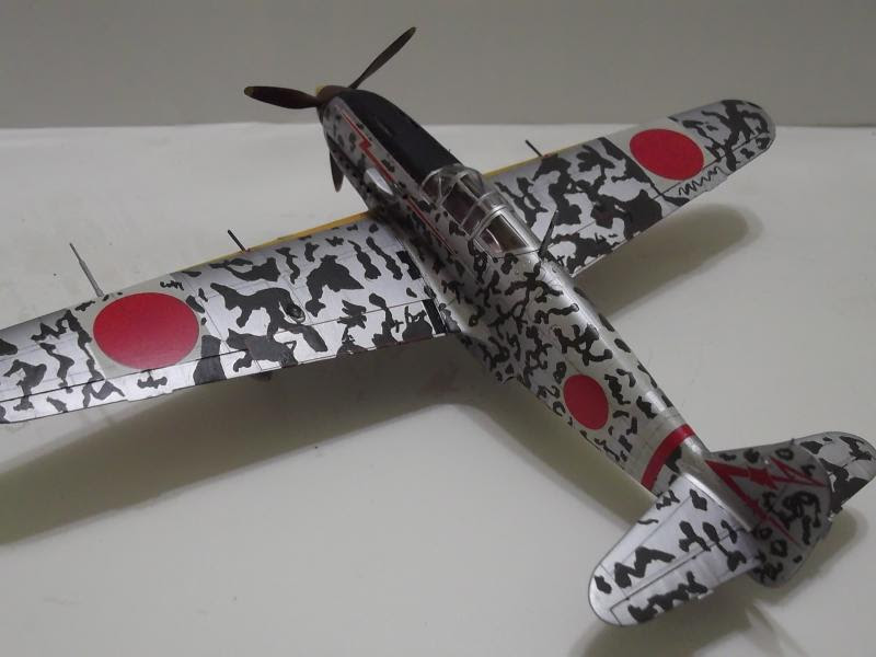
The odd duck among Japanese fighter planes of World War 2 (together with the early versions of the Yokosuka D4Y Suisei 'Judy' dive-bomber) by being powered with an inline engine, the Nakajima Ki-61 Hien was developed by the Kawasaki Aircraft Industries as a response for a 1939 tender by the Koku Hombu. The tender specified for two fighters powered by the Daimler-Benz DB601A engine, built locally as the Ha.40. The first, designated Ki-60 was to be a heavily-armed high-altitude interceptor, while the second, the Ki-61 was to be a general-purpose fighter intended to be used in an air superiority role at medium to low altitude. Unlike many other Japanese aircraft of the period, the Ki-61 was to be fitted with a self-sealing fuel tank (semi self-sealing for the wing tanks), armoured windscreen and armour plate behind the pilot. Armament was two 12.7mm machine guns on the upper fuselage and a 7.7mm machine gun in each wing.

The Ki-61 (or officially, Army Type 3 Fighter, Model 1) first flew in December 1941. Test pilots were enthusiastic about the self-sealing tanks, pilot protection and improved armament (Japanese Army fighters up to that time were mainly armed with two rifle-calibre machine guns only). However the top brass of the Koku Hombu, who still believed in highly maneuverable, lightly-armed fighters, like the Ki-43 Hayabusa, viewed the aircraft with some scepticism as it has a higher wing loading than previous fighters. To address their concern, a fly-off was staged between the Ki-61, Ki-43, a pre-production Ki-44 Shoki, a Lavochkin LaGG-3 (flown to Manchuria by a Soviet defector), a Bf 109E and a captured P-40E Warhawk. The results showed that the Ki-61 was faster than the other planes, and being inferior only to the Ki-43 in maneuverability. Production was planned to start in April 1942, but following delays, it was only started in August 1942.   

The Ki-61 Hien (Swallow) actually first saw action in April 1942 when the prototypes were thrust into action over Yokohama during Doolittle's Raid on the 18th. The operational aircraft first saw service with a training unit, the 23rd Chutai and first saw combat service in the South-West Pacific with the 68th and 78th Chutais based in Wewak, New Guinea and Rabaul, New Britain respectively. The jungle and tropical conditions, together with lack of spares undermined the efficiency of the new fighter. Like many new aircraft being rushed into service, the Ki-61 suffered teething problems and the engine, unlike the original DB601, was not reliable through poor quality control at the factory. Despite the problems, the Hien was considered with some concern by the Allies, as unlike against the Ki-43 and the Japanese Navy's A6M, they cannot escape from the Hien by simply diving. The Hien was also also used elsewhere in the Pacific Theatre and as B-29 interceptors over the Home Islands. As interceptors, the Ki-61 was also grouped in special units which used ramming as part of their tactics. The Ki-61 looked so different from the other Japanese fighters that Allied pilots misidentified them as German or Italian in origin. In fact, Captain C. Ross Greening, who took part in the Doolittle Raid, took the intercepting prototype Ki-61s as Bf 109s. Based on this observation and the perceived origins of the fighter, the US War Department gave the codename 'Mike'. Later, it was finally revised as 'Tony' as the Ki-61 looked like an Italian-designed fighter, specifically the Macchi MC.202 series.

A total of 3,159 Ki-61s were built with the Ki-61-I being the main production version. The Ki-61-I Ko (or 'a') was armed with two 7.7mm Type 89 machine guns in the wings and two Ho-103 12.7mm machine guns in the upper fuselage decking. The Ki-61-I Otsu ('b') replaced the rifle-calibre wing machine guns with the H0-103 heavy machine guns. The unreliability of the tailwheel retraction mechanism caused the tailwheels to remain fixed in the 'down' position for this (and the Hei) variant. The Hei ('c') version replaced the wing machine guns with German MG 151/20 20mm cannons. As only 800 weapons were managed to be imported into Japan by U-Boats, just 368 Hei variants were built (the remainder of the cannons were utilized as spares). The Tei ('d') version have a revised armament arrangement by mounting Ho-103 12.7mm machine guns in the wings and a single Ho-5 20mm cannon in the fuselage. The final Ki-61-I version was the KAId  interceptor, with two 12.7mm machine guns in the fuselage and two 30mm cannons in the wings. The Ki-61-II was supposed to be an improved version, featuring a more powerful engine, the Ha-140. The engine was however even more unreliable than the Ha-40 and with the destruction of the Asahi plant making the engines in 1944, an alternative powerplant was sought, creating the Ki-100 fighter.

The Kit
The kit I build was the 2005 reboxing of the 1/48 Hasegawa kit originally released in 1994. This particular reboxing is of the 'Hei' or 'c' version of the Ki-61-I.  The parts have nicely engraved (and raised, where appropriate) surface details with thin trailing edges of the flying surfaces. The cockpit has adequate details to show especially when the modeler decides to use the kit's one-piece canopy. The parts count are relatively low for a 1/48 aircraft kit but does not sacrifice the details (of course modelers can spruce up their kit further by using aftermarket resin and PE parts). The decals provide markings for two aircraft from the 244th Sentai, a premier Ki-61-I operator during the war. Unlike earlier Hasegawa decals, the white portions are white instead of ivory for 1990s Hasegawa kits. The options are for:
1. Captain Fumisuke Shouno, Chofu Airbase, February 1945; and
2. Captain Yukio Ishioka, Chofu Airbase, 1945

Construction
As usual with aircraft kits, construction starts at the cockpit. The cockpit parts were painted Tamiya XF-59 Desert Yellow with the various detail parts in XF-64 Red Brown, XF-69 NATO Black, X-7 Red and XF-3 Flat Yellow.  A hole was drilled into the left fuselage in order to accommodate the oil cooler intake. Then I moved to the radiator assembly which consists of four parts. While the instructions suggested silver, I painted the radiator flat black and then drybrushed silver onto it. The sidewalls were then cemented onto their respective fuselage halves with the dashboard, cockpit floor and pilot's seat and the radiator assembly cemented onto the right half of the fuselage. The fuselage halves were then mated together using Tamiya Extra Thin Cement. There is a little gap on the fuselage spine, but I add a bit more cement and squeeze the halves that bit more. The resulting ooze were left to dry and was later scraped off with a sharp hobby knife. The front fuselage decking was then cemented onto the fuselage but I did not attach the gun barrels, gunsight and exhaust manifolds at this time. A hole was also drilled into the fuselage decking to accommodate a, uh, 'thingy'.

Moving on to the wings, I first drilled holes on the upper wing halves in order to fit Parts Q2 and Q3 (cannon breech covers on the real plane) and on the one-piece lower wing half, to accommodate the drop tanks. The wing halves were mated together and the wing assembly was then fitted to the fuselage. There is a slight gap at the upper wing roots which was swiftly dealt with putty. The cannon barrels were however left off at this stage. The tailplanes were then cemented onto their places and this was followed by the radiator flap. returning back to the cockpit, after painting the rear cockpit decking the same colour with the interior, the parts were fixed in place, at the same time not forgetting the gunsight. This was followed by the canopy, which was masked beforehand. The rest of the parts were left off until after painting.

Painting and Decaling
As mentioned before, Hasegawa provides two marking options; the first in plain natural metal and the other with green splotches all over the fuselage. The kit instructions specify Mr Color 8 Silver which I think does not look right in simulating natural metal. Yet I have ran out Tamiya AS-12 Bare Metal Silver and end up using TS-30 Silver Leaf anyway. The anti-glare panel was painted XF-69 NATO Black. Having done the basic painting, I decided to do the second option with its camouflage pattern. Looking at the instructions, the green splotches were painted over the air defence white bands and around the 244th Sentai's tail markings. So, I modify my approach by applying the Hinomaru/AD bands and the 244th Sentai's markings first. I let the decals settle and then started painting the camouflage pattern using Tamiya XF-13 JA Green. Once the paint had dried, I applied the rest of the decals.The wing leading edge ID bands, together with the forward part of the propeller spinner,  was painted using a mixture of Tamiya XF-3 Flat Yellow and XF-7 Flat Red. The panel lines were highlighted with a 2B pencil.

Finishing
The drop tank halves were mate together and painted Tamiya XF-53 Neutral Grey; when dry they were attached to the pylons and cemented to the wings. Finally the smaller or the more fragile parts can be permanently fixed to the model, starting with the fuselage machine guns and the exhaust manifolds. Tamiya Weathering Master Soot was then applied to simulate exhaust deposits on the fuselage. This was followed by the more vulnerable parts like the landing gear assembly, tailwheel, radio mast, pitot tube and the wing cannon barrels. The propeller was then fitted. Finally Tamiya TS-79 Semi-Gloss was sprayed and when dry, the masks were removed, finishing the build.

Conclusion
Another fine 1/48 aircraft kit from Hasegawa. It was easy to build and have no real nasty surprises (the gap on the wing root is just a minor annoyance). I guess there is not even the need for aftermarket stuff for this model (with the exception of decals probably). When displayed with its other Japanese comrades, it immediately attracts attention due to its inline engined nose profile.  


Wednesday, 23 July 2014

Kalashnikov On Tracks


Historical Background
The T-55's genesis goes back to the T-44 of 1943-1944. The T-44 has the same performance with the T-34/85 but with greater protection thanks to space-saving torsion bar suspension, transverse engine mount and the deletion of the hull machine gun. However the turret was incapable of mounting guns larger than the 85mm gun although a 100mm gun was desired. The T-44 was redesigned into the prototype T-54 in 1945 by the OKB-520 design bureau, based at Factory No. 183 (Uralvagonzavod) at Nizhny Tagil. Originally having the same turret shape as the T-44, it was later redesigned with a dome-shaped turret. Armament was a 100mm D-10T tank gun and two 7.62mm machine guns.  Armour was initially 180mm thick for turret front and 120mm for hull front (the armour was thickened for subsequent variants). In tests conducted with nuclear weapons, it was shown that a T-54 can survive the blast of a tactical nuclear weapon of between 2 to 15 kilotons at a range of more than 300 meters from the epicentre, although the crew could only survive at a range of no less than 700 meters. Therefore, in order to improve protection, the KB-60 design bureau at Kharkov studied a new NBC system called PAZ (ProtivoAtomnaya Zashchita). KB-60 completed its tests in 1956 and a new set of blueprints and the range of modifications needed were sent to Uralvagonzavod.

The T-54M (Ob'yekt 139) was used to test the changes. It was also powered by a new V55 12-cylinder 38.88 litre water-cooled diesel engine generating 581 hp. Main armament was basically unchanged but ammunition capacity was increased from 34 to 45. new ammunition was also developed, such as the BK5M HEAT round which could penetrate 390mm of armour. The commander's TPKU vision device was replaced with either the TPKUB or the TPKU-2B while the gunner received a TNP-165 sight. The loader's hatch-mounted DShK 12.7mm AA MG was removed as it was deemed worthless against fast-flying jets. The turret has a thicker front (200mm) although the rear plate had to be thinned to save weight. The gun was fitted with a two-axis stabilisation as well as night-vision equipment. All these improvement resulted in Ob'yekt 155 and entered production on 1 January 1955 as the T-55. The T-55 was superior to the IS-series heavy tank despite being smaller and lighter-armoured. It has a better rate of fire, anti-tank capability and mobility. The heavy tank concept soon fell out of favour and the new concept of main battle tank began to emerge. In 1961, another round of improvements in NBC protection began in order to protect the crews against fast neutrons and gamma radiation. The system was characterised by a the addition of a POZ plasticised lead lining applied to the entire interior of the tank, requiring the enlargement of the driver's hatch and the coamings over the turret hatches. As an additional benefit, the liner also protects the crew against spalling. The PAZ/FPU chemical filtration system was also fitted and the co-axial SGMT machine gun was replaced with the PKT. T-55s with these enhancements were known as the T-55A. 

The T-54/55 family is mechanically simple yet robust. Compared to Western tanks, they are simple to operate and don't require a high level of education and training for their crews. The T-54/55 family has relatively low weight, allowing easier transport by rail and allows crossing of lighter bridges. They are also relatively small for a MBT, presenting a smaller target profile. While not a match for modern MBTs, armour and ammo updates may improve the old tank's performance that it cannot be dismissed on the battlefield. Nevertheless, the family has serious drawbacks. The small size is actually a double-edged sword - it restricts interior space and  crew comfort, constraining crew movement and slowing down the usage of equipment. The low silhouette also restricts the gun depression angle to just -5˚ (Western tanks usually can depress down to  -10˚) limiting their ability to fire from a hull-down position in a reverse slope. In the Red Army, the limited crew mobility inside the tank was partially solved by restricting the height of the crew members, a practice still continuing as the Russian Army is still operating the low-silhouette T-72/T-80/T-90. The armour, while thick enough to be impervious against most tank guns of the 1950s and the hand-held anti-tank weapons of the era (such as the bazooka, PIAT and RPG-2), became obsolete within 20 years of introduction. The side armour, thinner than the front, was vulnerable to LAW rockets, TOW missiles and even 76mm AP rounds, as proven during the Vietnam War.

In the early 1970s, drawing from combat experience of the T-55 users worldwide, the loader's cupola was refitted with either the DshK/KM 12.7mm AA MG or the 14.5mm KPVT AA MG to deal with attack helicopters. In 1974, the KTD-1 or KTD-2 laser rangefinder in an armoured box was fitted over the gun mantlet. The T-55/55A continue to get upgrades throughout their lives, such as better fire-control system, ATGM capability, ERA armour, suspension, tracks, RPG screen and various other additional capabilities. The T-54/55 was used in various conflicts, starting with the Invasion of Hungary in 1956. In Europe it was also used during the enforcement of martial law in Poland in 1981-1983, the Invasion of Czechoslovakia 1968 and the Balkan Wars of the 1990s. In the Middle East, they were used in the Six-Day War 1967, Jordanian Civil War 1970, Yom Kippur War 1973, Iran-Iraq War 1980-1988, Operation Desert Storm 1991 and Operation Iraqi Freedom 2003. In Africa, they were used during the Angolan Civil War 1975-2002, Tanzania-Uganda War of 1978-79 and the Libyan Civil War 2011. In Asia it was used during the Vietnam War from 1971, the Cambodian Civil War, Indo-Pakistani Wars 1965 and 1971, Sri Lankan Civil War and the Afghanistan conflict. In most cases, especially against the Israeli Defence Force, the T-55 were worse off against their Western-built counterparts although it was actually more have to do with their deployment and usage, as demonstrated during the Battle of Dezful between 5-9 January 1981 during the Iran-Iraq War, where the Iraqis managed to disable or destroy 200 Iranian Chieftain and M60A1 tanks, while losing 50 of their own T-55s.

The T-54/55 family can lay claim to be the most produced tank in history. For the T-55 series, 27,500 units were built between 1955 and 1981. Another 7,000 were built in Poland between 1964 and 1979 and Czechoslovakia produced 8,300 from 1964 until 1979. The Red Army have around 20,000 available should the Cold War turn hot and they still have around 3,000 by the time the Iron Curtain crumbled in 1990. Today perhaps around 500 are still in storage. The T-54/55 were also widely exported and used around the world, from Abkhazia to Zambia. Many of these countries have their own upgrade and modernisation programmes such as the Czech T-55AM, Egyptian Ramses II, 'Enigma' conversion of the Iraqi army, Pakistani Al-Zarrar, Israeli Ti-67 and Tiran series and also the Type 59 series, essentially the Chinese copy of the T-54, which also ran into the thousands. There are also variants such as the BTS-3 armoured recovery vehicles, MT/MTU-55 armoured bridgelayer, BMR-2 minelaying vehicle, OT-55 flamethrowing tank and BTR-T APC. The huge numbers plus age (in the later years) makes the family cheap and easy to purchase. It's simplicity also allows quasi-military forces with no formal training to operate them.

The Kit
With such a large number of vehicles in service with various nations, it is naturally assumed that the T-54/55 family (from here onwards, I would just refer them as the T-55) is a hugely popular subject. I guess that that's the truth but modelling companies were rather indifferent, especially in the popular 1/35 scale. Old hands such as Cookie Sewell mentioned Tamiya themselves produced a kit of the T-55 in 1967, but as with many of their kits of the same vintage, was awful. Then in 1989, at the time when the T-55 had been relegated to 'B' and 'C' Type formations of the Red Army, Lindberg came up with a T-55 which can also be made into a Israeli Ti-67. Having seen built-up examples in modeling magazines, they are also pretty awful, looking nothing like the real item. In 1992, ESCI produced their version the T-55. Like its predecessors, it also suffered from shape and accuracy issues. It however did not stop Italeri from re-issuing it in 2004. In 1999, Trumpeter and Lee showcased theirs. They generally look OK but still suffer shape issues, which, among others, was caused by the need for motorisation, like the Tamiya kits of the 1970s. Furthermore, Trumpeter's early kits were made from ABS type plastic which was very difficult to cement together. In 2001, SKIF from Ukraine brought the hope that an accurate T-55 finally emerged; being Ukraine-based they should have access to the real thing to make their measurements. Instead they were so disappointing that Cookie Sewell likened them as more as an insult than disappointment. Dragon, that co-leader in 1/35 tank/AFV model industry, advertised for years that they would come up with a T-55 (and I followed the 'New Kit News' section of the Perth Military Modeling Society website month after month) but eventually dropped the plan and continue with their empire of WW2 German AFVs.

Finally in 2002, rather like a bolt of of the blue, Tamiya announced a new tool T-55A. It caused quite a stir (what an understatement!) in the modeling community as (1) it is a Tamiya kit and (2) since it is a Tamiya, everybody's pinning their hopes that this The One after a decade of disappointment (following SKIF's T-55). When it finally hit the market, Tamiya kit 35257 did prove that it IS The One. The kit is moulded in olive green plastic and consists of 275 parts, a small sheet of mesh, a length of twine to make the tow cables, the usual Tamiya poly caps, a small decal sheet and the instruction booklet of course. The moulding is up to Tamiya's usual high standard. The lower hull is in one piece and has all the details, despite being mainly out of sight on the completed model. And, according to online reviews, the dimensions and details of the kit is almost spot-on with optional parts for depicting Polish- or Czech-built machines. The turret have subtle cast texture while having very nice weld beads around the turret top. The barrel is of the usual two-piece assembly which needed careful assembly but nothing unusual there. The mantlet dust cover has very good fabric effect although the trade-off is that the gun would be in a fixed position. Tamiya provided multiple commander's and loader's hatches, depending on which version the modeler makes. There is however no plumbing for the track guard-mounted fuel tanks; the modeler either have to fashion one by himself/herself or get an aftermarket one (or just leave them as they were). The one-piece tracks, while having good detail, is not really suitable to mimic the droopy T-55 tracks. The decal sheet contains markings for two Soviet tanks (T-55A mod. 1962 and T-55 mod. 1970), two Polish tanks (T-55 mod. 1970 and T-55A mod. 1970) and a solo Czech T-55A mod. 1970. Again, they are of the usual Tamiya standard.

Construction
The first step was concerned with the assembly of the wheels. They are of the usual Tamiya style of two halves with a polycap inserted in-between the halves. The idlers are of the 'scalloped' type while the T-55's distinctive 'starfish' pattern roadwheels have superb details. The suspension, together with the rear hull plate and the forward plate, together with the dozer mounting points were then cemented onto the hull. The suspension arms were then checked to ensure that the all the wheels would touch the ground. The already complete wheels were then mounted onto their mountings to double-check the 'sit' of the suspension arms and were then removed for painting. Next, the fuel drum racks were slid into their places and secured with Tamiya Extra Thin Cement. While the flanges do add strength to the mounting, I have to exercise care when handling the model for the rest of the build stage, to avoid breaking the fuel drum mounts. The lower hull was more or less completed at this time and I moved on to the upper hull.

Tamiya provided the upper hull in one piece, with the track guards moulded together. There aren't many parts to add at this stage, just a small number of track guard supports, the upper half of the exhaust....and Parts D27 and D31 (I can't remember what they are called!). The upper hull was cemented onto the lower half....and I found that there are gaps at the corners of the hull. Again, I believe that it has nothing to do with Tamiya's engineering. Anyway, I just fill it with putty - problem solved! Now the rest of the upper hull parts can now be cemented. Here, Tamiya provided optional parts for the T-55 and T-55A, which is the driver's hatch; either D42 for T-55 or D42 and D40 for T-55A, and also for Soviet or Warsaw Pact-built vehicle (the headlights and their brush guards). At this juncture, I decided to build a T-55A, so the bulged driver's hatch was used.  The track guard-mounted storage boxes were then assembled and then cemented onto their places on the left track guard. The external fuel cells were mounted onto the right track guard. Here, Tamiya omitted the plumbing which connects the tanks to the engine. They are not difficult to fabricate using brass or lead (soldering) wire, aluminium foil and scrap plastic plus there are plenty of the plumbing arrangement photos on the internet. Using photos and diagrams available on the internet, I used 0.3mm brass wire to create them - the piping bears the hallmarks of my general clumsiness i.e the straight sections are not straight! Furthermore I couldn't find anything suitable to replicate the fasteners (or whatever they're called) so my external fuel piping simply consist of the plain 'pipes' only. Also, I think 0.3mm gauge wire is too thin; perhaps 0.5mm is better-looking plus I need a better material such as soldering or steel wire. Finally, for the engine deck, I cut the provided mesh using the template included in the instructions and glued them to the frame using white glue. Needless to say, a PE grille is a better substitute. The rear fuel tanks were then cemented into position. Their fit is OK with just a hairline seam to be cleaned up.

I then turned my attention to the turret. Before working on it, a number of holes need to be drilled according to the version you choose. After originally decided to build a T-55A by using the bulged driver's hatch, I then decided to make a Soviet T-55A with AA MG. It is not in the options but I think it can be done with the parts provided in the kit.  The turret shell was mated with the bottom and then I went straight to adding the commander's and loader's hatches. I made a mistake though, one which I only realised when writing this piece. While the anti-radiation cladding was placed between the hatches, I then however, rather absentmindedly referred to Option B in the kit's instructions (a Soviet T-55 with AA MG). To build a DShK-equipped T-55A, I should have referred to Option 'C'. Yes, that option is for a Polish-build tank, but with the benefit of hindsight, I believe that the distinctive feature of a Polish-built T-55/T-55A is just the storage box on the left of the turret. So I end up having a T-55 with the T-55A's turret cladding and driver's hatch! Murphy's Law was in full swing here, and as Forrest Gump said, s**t happens!!!

Tie-down hooks were then cemented to the rear of the turret using the faint placement lines as guide. Again, they are best replaced with copper wire. Moving back to the front of the turret, the gun barrel halves were cemented together. There is a hairline seam but nothing serious here. The muzzle end is separate and fit nicely to the barrel. The barrel assembly was then mated to the moulded dust cover. The provision of the dust cover means that the gun is fixed at 0˚ angle. I have no issues with that especially when the dust cover have very nice fabric effect. The searchlight was assembled and cemented onto its place, together with the mechanism to move it in unison with the gun. The DShK AA MG and the snorkel tube were assembled but were left off until after painting. I have however lost the gun's hand grip and substituted it with a 0.5mm rod. A piece of copper wire from a speaker cable was used as additional detailing, that is, as a control cable from the hand grip to the trigger. The turret handrails were also left off at this stage.

Painting and Decaling
Like their World War 2 predecessors, there are a number of colour combinations which can be used to replicate the colour of post-war Soviet tanks. For this build, I decided to forego my colour mix for the Russian Green and decided to use Tamiya XF-65 Field Grey, as used by many modellers I have seen on the internet. The model was painted in this colour, which was lightened with 20% Flat White for scale effect. Once the paint has cured, I mixed some Tamiya XF-5 Flat Green with some 90% thinner to make a filter layer for the Base colour. The tyres were painted Tamiya XF-63 German Grey and the machinegun XF-69 NATO Black. When dry, I rubbed some powdered graphite to the MG for that metallic sheen. As photos of the real tank shows it to have a slight sheen, Tamiya TS-79 Semi-Gloss Clear was sprayed onto the model. The tracks were painted XF-64 Red Brown and were then washed with AK Interactive's Track Wash.

As mentioned before, I had originally intended to build a Soviet T-55A with AA MG (or a Soviet T-55A Model 1970) and therefore I did not intend to use any of the kit decals. Even though I have built a T-55 Model 1970 (more or less) which is Option B of the  marking scheme, I decided to finish my model as something else. With thousands of tanks in Soviet service and with practically no distinctive individual markings, I can practice artistic licence with plenty of freedom here. Browsing the internet, I came across a number of photos of T-55s of the Soviet Naval Infantry during the Cold War. The tanks have the three-digit identification numbers common to Soviet AFVs plus the Soviet naval ensign on the glacis plate and the side rear of the turret. IIRC, the three-digit ID number is not arbitrary and may change during deployments or exercises. Just to be different, I used the spare turret number decals from my old Tamiya T-62A kit. Despite their age, they are still good and apply easily. I used the large numbers and tactical markings for the turret and smaller numbers for the searchlight and the glacis plate. For the Soviet Naval Ensign, I used the one available from Dragon's Scud launcher kit. The one in the Dragon kit has the 'flagpole' in the design but photos show that both designs - with or without the 'flagpole' were used. Unfortunately, like older Hasegawa decals, the white portion of the decal was more ivory than white. No Naval Ensign decals were placed at the rear quadrants of the turret as Dragon provide only one decal suitable for placement there. It wasn't a problem anyway as there are photos showing Morskaya Pekhota tanks without them. All decals were then subjected to Mr Mark Softer treatment.

Finishing
The remaining parts such as the handrails, snorkel tube and the AA machinegun assembly are fixed to the model. The unditching log was painted a base colour of Tamiya XF-55 Deck Tan and washed with XF-59 Desert Yellow. Afterwards I drybrushed XF-64 onto it. The spare Ammo boxes on the turret side were also painted XF-65 Field Grey with the straps painted Mr Color Khaki. The model was then subjected to the usual wash process. The wheels and tracks were then permanently fixed to the model. To create the draped effect of the 'dead' tracks, I superglued the upper run to the tops of the roadwheels. It looked passable enough, although as stated before, workable track links were the best.  For weathering, I decided to add mud to the lower hull and tracks. This time I mixed Mr. Surfacer 500, Mig Productions' European Dust' pigment and lacquer thinner and apply them all over the underside of the model using an old brush that's on its last legs (or bristles to be exact). I only apply a thin mix/layer this time and to add some texture, I stipple the wet mixture with another old, stiff brush. The model was then set aside to dry. Then I washed the 'mud' with Mig Productions' Earth Effects wash mix. Afterwards, I mixed a thin slurry of water and the same pigment powder and apply them on the tracks and the underside of the track guards. Then I mixed a semi-dry mixture of pigments and enamel thinner and apply them sparingly on the tracks, to mimic mud stuck in the tracks' groove. Finally I apply Tamiya Weathering Master Soot on the exhaust port.

Conclusion
Without doubt, one the best (some consider it to be THE best) Tamiya kit so far, even though many modellers have to wait for 30-something years for it. All the parts were finely moulded and of course they feature excellent fit, allowing an easy build. While there are many permutations of the basic tank, Tamiya has covered the main variants, mainly with the alternate turret hatch options. Soon after the kit hit the market, aftermarket manufacturers also follow suit with various PE, track and also conversion sets. As stated before, the kit just need a good separate track links, preferably in metal to more accurately depict the sag of the dead tracks. The external fuel plumbing also need to be added, either being scratch-build or using aftermarket set, to more accurately depict the tank. Tamiya have also included metal separate track links (read : Friulmodel) and also with PE and metal barrel in special boxings of the basic kit. They have also since released two more T-55 based kits : the Iraqi Enigma T-55 and the Israeli Tiran 5.  Too bad I have run out of space in my display cabinet!


Sunday, 6 July 2014

Prince Char-Ming


Historical Background
In 1919, the French General Jean Baptiste Eugene Estienne wrote in his memo entitled MĂ©moire sur les missions des chars blindĂ©s en campagne, the concept of Char de Bataille (battle tank) that would be able to accomplish a breakthrough of the enemy lines by destroying fortifications, gun emplacements and the opposing tanks. In January 1921, a Government commission initiated a project for such a vehicle. The specifications include fixed armament (to save costs), a weight of 13 tonnes, maximum armour thickness of 25mm, a low hull so that the gun could fire into vision slits of bunkers and a small machine gun turret to ward off infantry attacks. It should also function as an armoured observation post. Two variants were envisaged - a close support tank with 75mm howitzer and an anti-tank version with a 47mm gun. The project attracted interest from the French industry and four prototypes were submitted : Renault and Schneider co-operated and submitted the SRA and SRB, Forges et AciĂ©ries de la Marine et d'HomĂ©court (FAMH, also known as Saint Chamond) submitted one and  Forges et Chantiers de la MĂ©diterranĂ©e (FCM) submitted their FCM 21 design.

In the spirit of the so-called 'Estienne Accord' which discouraged industrial competition among the defence companies, FCM was asked to give up their patent rights to the Army. In return, they were promised a large order of 1,000 vehicles of which Renault and Schneider would build 500 each, FAMH and FCM 125 each, Delaunay-Bellville (of which their enlarged FT-17 design was rejected earlier on) 83 and the remaining 167 would be alloted at the Government's discretion. On 13 May 1924, all the prototypes were presented at the Atelier de Rueil and in March 1925, General Estienne decided to base the production model on the SRB as regards the general form and mechanical parts with the gun and tracks developed from the FCM design and FAMH suspension. Armour was to be increased to 40mm. In November of the same year, Renault was ordered to build a wooden mock-up and in January 1926, three prototypes, each built by Renault,  FAMH and FCM, were ordered.

These prototypes were built between January 1929 and September 1930 and were used in the test programmes. By that time, the vehicle was known as the Char B (the 'B' however merely refers to a general classification code rather than 'Bataille') and was used not only for technological experiments but also in tactical ones. In the course of the programme, the prototypes were extensively reworked to meet changes in specifications. And on 6 April 1934, the first order was made for seven Char B1 (again the B1 indicates that it was one of simultaneous projects to improve the Char B). The Char B1 were built by Renault (182), AMX (47), FCM (72), FAMH (70) and Schneider (32). However, with a unit cost of 1.5 million francs, the order had to be cut to 400.

The B1 had 40mm of armour on the front and sides. It was armed with a 75mm ABS 1929 SA 35 howitzer mounted on the right-hand side of the hull front, a 47mm L/27.6 SA 34 in a fully-rotating APX 1 turret and two Chatellerault M1931 7.5mm machine guns. Ammunition capacity was 50 rounds for the 47mm gun, 80 for the 75mm gun and 4,800 for the machine guns. The crew consisted of the driver, who also acted as the hull gunner and a loader serving the hull gun. The remaining two crewmembers were the radio operator and the commander, who also has to act as the loader and gunner for the turret gun. The commander was considerably overburdened especially if he is the platoon commander, commanding other tanks. A total of 35 B1 were built. The main production version was the B1 bis: 369 were built between April 1937 to June 1940. The B1 bis featured a thicker armour (60mm) and the APX1 turret was replaced with the APX4, armed with a longer-barreled L/32 SA 35 gun, improving its anti-tank capability.

The general appearance of the B1 reflected its long gestation period stretching back to the 1920s. Its large tracks, going over the hull was reminiscent of the rhomboid British heavy tanks of World War 1. This similarity was partly as a result of the requirement of the B1 as an assault tank (or char de rupture), optimised for punching holes into the enemy's fortifications, including good trench-crossing abilities.  Fuel consumption was bad, necessitating frequent refuellings and therefore limiting its operational capability. In actuality, despite its supposed role, the B1s formed part of the Divisions CuirassĂ©es de RĂ©serve (DCR), which lacked strategic flexibility and thus were intended for the second phase of an attack. The 47mm turret while reasonably effective at the time, was an ergonomic nightmare (as mentioned beforehand). At the start of the Phoney War, the B1 were grouped within the DCR, forming the second echelon of an assault, while the initial assault was to be led by cavalry Somua S35 tanks. In May 1940, three DCRs, each with 69 tanks were mobilized and part of the 37ᵉ Bataillon de Chars Combat (BCC) have their B1 tanks rearmed with the SA 35 guns.

After Operation Fall Gelb began, four more DCRs with 52 B1 each were constituted, together with five Compagnie Autonome de Chars (Autonomous Tank Companies) with 56 B1s with another 34 in the 28ᵉ Bataillon de Chars de Combat. The B1s were used in countering the German assault, but with inadequate air cover, the Allied vehicles became victims of Stuka attacks. Bad deployment also resulted in these tanks being used as plugs in the defensive gaps. Their sturdiness however resulted in some success against the German panzers such as the-then Colonel Charles de Gaulle's counter-attacks at Iaon and Montcornet and the defensive stand at Hanuut and Stonne. At the latter, a single B1, named Eure, commanded by Captain Pierre Bilotte attacked and destroyed thirteen Panzer III and IV tanks before having to withdrew with 140 hits on his tank. Along with the British Matilda tanks, the B1 is the most feared tank by the Germans as the 37mm gun arming the Panzer IIIs and the anti-tank units were unable to pierce the frontal armour. The majority of B1s lost in the Battle of France however were not through enemy action but due to the lack of fuel and mechanical problems.

Following the fall of France, the Germans captured hundreds of Allied tanks, including 161 Char B1 bis tanks. These were absorbed into German service as the Panzerkampfwagen B-2 740(f) and were used in second line and training roles. Sixty were converted into flamethrowing tanks (Flammwagen auf Panzerkampfwagen B-2 740(f)) and sixteen converted to carry the leFH 18 105mm field gun. In German hands, the tanks took part in the Balkans Campaign and Operation Barbarossa. They also form part of the garrison units in France and the Channel Islands. When France was liberated in 1944, some of the B1s were recaptured. These were used provisionally by the French Resistance against pockets of German forces, such as those defending Paris. The B1 was also used by the 2nd Company of the 13th Dragoon Regiment of the Free French forces from October 1944 until its disbandment in April 1946.

The Kit
In 2006, Tamiya delighted the modeling community by announcing a new 1/35 kit of the Char B1 bis, in the wake of Hotchkiss H38/39 family from Bronco and Trumpeter. The kit contains 220 parts moulded in beige coloured plastic plus 130 sprue-less individual track links moulded in chocolate coloured plastic. Also included are a few poly caps, two lengths of heavy chain and the usual decal and instruction sheet plus a small sheet describing the action at Stonne. The colour guide is separate from the instruction sheet and is printed in full colour. Scanning through the parts and the instruction sheet shows that Tamiya missed the six boltheads on the 75mm gun mantlet and also the 'pig tail' lifting hook on top of the mantlet. The individual track links are of snap-together type and require only a minimal clean-up of the pour plug by light sanding. A sitting tank commander figure is also included, to be placed in the turret hatch. He looks rather emaciated though. Decals provide markings for four tanks:

- 257 'Bourrasque', 2nd Section, 1st Company, 15ᵉ BCC, 2nd Armoured Division, France 1940
- 481 'Vercingetorix', 3rd Company, 46ᵉ BCC, 4th Armoured Division, France 1940
- 467 'Nivernais II', 2nd Section, 3rd Company, 37ᵉ BCC, 1st Armoured Division, France 1940
- 205 'Indochine', 3rd Section, 3rd Company, 15ᵉ BCC, 2nd Armoured Division, France 1940

Selection for the markings has to be made partway through the build as the tanks feature different track guards and exhausts.

Construction
Construction starts with the roadwheels - 32 of them. Two halves each. Each half has excess sprue tags which needs to be cleaned. The wheels were then place d into a u-shaped gondola which would then be cemented onto the lower hull. I believe that this could be a recipe for disaster (or at least very tricky handling). So, although Tamiya recommends that the wheels are to be left unglued so that they could turn freely, I glued them with the sprue tags intact, but positioned so that they would be hidden inside the hull. The next step was concerned with the sprocket and idler wheels and also the forward suspension, which includes the 75mm howitzer assembly. The howitzer was secured with three poly caps, which allows it to traverse, elevate and depress, albeit at restricted angles, just like the real thing. The uprights together with the idler wheels (and the howitzer) were then need to cemented onto the lower hull, otherwise I won't be able to push them in if done later. The rest of the lower hull parts were then cemented.

Before working the one-piece upper hull, 26 1mm holes were drilled into the specified areas to fit various hull fittings. Then various  fittings were added. including mud chutes, rear hull fittings, track guide and various hatches and access panels. About the mud chutes, the 'intake' apertures are actually moulded shut and detailers might want to drill them out for that extra detail. The upper hull assembly was then cemented (I used Tamiya Extra Thin Cement) onto the lower half. They fit perfectly with no gaps present. The basic hull construction was then finished with the addition of the glacis plate and the mantlet for the howitzer. As mentioned before Tamiya omitted the six boltheads and the 'pig's tail' on top of the mantlet. There should also be weld beads surrounding the mantlet cover. While I did notice those omissions, I entirely forgot about them in the euphoria of the build and only realised after the model has been painted!

Next I assembled the tracks - I wish every model company could have this kind of track for all their models. The links came off the sprue and simply click together. The basic assembly took just 10 minutes with just that light moulding pips to be cleaned up. The tracks however were a tight fit around the hull, so I checked the drape of the tracks around the hull, subtracting the excess when necessary (it took 61 links for each run actually). The tracks were then removed for painting and to be added later. Turning my attention back to the hull, the track guards were attached. This is where the decision to build which marking was made - I decided to build Option B - 'Vercingetorix', which have the track guards without gaps where they meet the hull. There are also two choices for the exhausts; as I have already chosen 'Vercingetorix', the extended exhausts with their appropriate ends were used. The exhaust shrouds were cemented to the piping but I only dry fit the exhaust assembly to the hull to ease painting.

The final step before the painting stage was the assembly of the turret. First, the sub-assembly of the 47mm gun and the commander's (or was it just the periscope's?) cupola. The latter came in two halves which need to be cemented carefully to avoid visible seams. I simply add a bit more cement than usual and when the halves were mated together, the excess cement oozed out and left to dry. It was then scraped off using the hobby knife and the leftover was sanded. The turret was then assembled with the turret hatch in the open position as I intend to use the commander's figure. The cupola was then put on the turret unglued as it was designed to be rotateable. It is now time for painting.

Painting and Decaling
'Vercingetorix' was painted in a 3-colour (4 if you count the demarcation line between the colours) called Puzzle 1er Type which consists of vert olive mat foncé (matt dark olive green), brun (brown) and ocre jaune (very light brownish sand). Tamiya's interpretation of those colours are XF-58 Olive Green, XF-9 Hull Red and 2 parts XF-59 Desert Yellow mixed with 1 part XF-60 Dark Yellow. The demarcation line was XF-69 NATO Black. I first painted the tank overall ocre jaune. This was followed by hand-painting the camouflage colours. The demarcation line should be a relatively thin line, but as you can see, some are quite wide. This caused by the paintbrush I used, which was not small enough for such application. On hindsight, I should have used a felt-tip marker pen for those lines, or overpaint the excess using any of the base colours where appropriate.

The decals were then applied. They were of the usual Tamiya quality, which is rather thick. They were subjected to repeated applications of Mr Mark Softer especially those running over rivets, hatches and panel lines. For positions against the latter two, the decals were 'persuaded' to get into the recesses using a suitable tool such as a (discarded) ball-point pen tip. To unify the colours, the model was then subjected to a filter wash of XF-57 Buff. Once dry, it was subjected to a pin wash to help pop-out the raised details. The tracks were painted XF-64 Red Brown and then washed with AK Interactive's Track Wash. It was then dry brushed silver at the contact points with the ground. The heavy tow chains were also washed with the Track Wash, as I do not have any blackening / 'antiquing' liquid in my arsenal - I think the effect was the same though. The exhaust pipes were painted XF-64 and once dry were randomly dabbed with Tamiya Weathering Master Rust. BTW, the tank was named after Vercingetorix, the Gallic chieftain leading their revolt against the Roman Empire from 52BC to 46BC.  

Finishing
The remaining loose parts can now be permanently attached. Not many of those, just the aerial base, turret guard rail, the exhaust assembly and the tracks (the tow chains are to be attached later). I then moved on to the weathering stage. I have seen photos of B1 tanks with dirty staining on the hull, probably from the oil used in lubricating the tracks, sometimes looking quite severe. I simulated this staining using a combination of Tamiya X-19 Smoke and Tamiya weathering Master Soot. These were applied in vertical streaks down the upper half of the hull and also around some maintenance hatches. X-19 Smoke was also used to mimic lubricant leak around the hub of the sprocket wheels. Next, I applied AK Interactive Earth Effects wash at the lower hull, wheels, tracks and the mud chutes. This was followed by a 'wet' application of Mig Productions' European Dust pigment; the excess of which was removed using a stiff brush. The chains were then hooked onto the towing eye and hung over the hooks at the rear of the hull using Tamiya's instructions as guidance. The commander's figure was assembled and painted using Tamiya acrylics as instructed although I substituted X-9 (Gloss) Brown with X-22 Clear to mimic the sheen of the tanker's leather jacket. He was then placed inside the turret hatch. Finally, a length of copper wire was cut, painted black and attached to the aerial base, finishing the build. And yes, I notice that the aerial is not straight!

Conclusion
I believe Tamiya's Char B1 bis is among the easiest kit I have ever built. While it was easy to build, the kit did not sacrifice the details (OK, there are some omissions, but those are relatively minor and easily corrected). It already looked good when built OOB and I think all it needs to look great was just the addition of PE track guards, PE (or home-made) exhaust guards and the addition of a bit more rivets, boltheads and weld beads. For those who must have a black crossed tank in their collection, this kit allows easy conversion to PZkPfw B-2 standard, or use Tamiya's follow-on PzKpfw B-2 kit. While it costs a bit more, I think it was quite justified. A must-have kit for anyone who wants to complete his/her collection of World War2 tanks. Now, how about a better-detailed, modern moulding technology Somua S35 tank?