Showing posts with label Gulf War 2. Show all posts

Wednesday, 6 May 2020

The Mudhen Returns To Mideast


Historical Background
The F-X fighter programme which resulted in the McDonnell Douglas F-15 Eagle was specifically tailored for air superiority mission with little consideration for air to ground missions (hence the phrase 'not a pound for air to ground'). The opposition by the F-15 Special Project Office in The Pentagon caused McDonnell Douglas to quietly work on the interdiction version of the Eagle envisioning it as a replacement for the F-111, the (then) remaining Phantoms and to augment existing Eagles. In 1978, the USAF initiated the Tactical All-Weather Requirement Study (TAWRS) which, amomng others, looked at McDonnell Douglas's proposal. The study recommended that the Eagle as the USAF's future strike platform and in 1979, McDonnell Douglas and Hughes teamed up to develop the F-15's air-to-ground capabilities. An F-15B, serial number 71-0291 was modified to act as a demonstrator and was first displayed at the Farnborough Air Show in 1980.

In March 1981, the USAF announced the Enhanced Tactical Fighter (later renamed Dual-Role Fighter) programme to procure a replacement for the F-111. The programme envisioned an aircraft capable of flying deep air interdiction missions without additional electronic support and fighter escort. McDonnell Douglas submitted its now-named F-15E while General Dynamics submitted the F-16XL. After a lengthy evaluation programme, the F-15E was chosen as the winner on 24 February 1984. Key factors in the selection of the F-15E over the F-16XL include lower development costs, belief that the F-15E had future growth potential and twin-engine redundancy. The first officially-completed F-15E was first flown on 31 March 1987 and the first production aircraft was delivered to the 405th Tactical Training Wing at Luke AFB, Arizona in April 1988. The USAF contracted for a total of 400 F-15Es (later revised to 392).

The F-15E Strike Eagle, although optimized for air-to-ground missions, retains the full air-to-air combat capabilities of the original Eagle. Although the prototype was basically a modified F-15B, production F-15Es have significant structural changes and using much more powerful engines (originally Pratt & Whitney F100-PW-220 rated at 105.7 kN with afterburner, later the Dash 229 version rated at129.7 kN with afterburner). The rear cockpit position is 'missionised' to allow the WSO to work the air-to-ground avionics (while still having flight controls, allowing the WSO to pilot the aircraft should it become necessary). Conformal Fuel Tanks (CFTs), containing 2,800 liters of fuel (in addition to the original  internal tankage) on either sides of the fuselage gave the Strike Eagle its long legs at a slight cost in drag and performance. The APG-70 radar system incorporates Doppler Beam Sharpening, Mapping and Synthetic Aperture Radar modes to enhance operational capabilities. One feature of the system is that it can 'freeze' the air-to-ground radar map and then goes back to air-to-air mode to check for aerial threats. In addition, the WSO is able to designate ground targets while the pilot engages aerial targets. The APG-70 was replaced by the APG-82 AESA radar beginning in 2014.

The F-15E carries most air-to-ground weaponry in the USAF inventory, from 'dumb' Mk 80 series bombs to precision strike JDAMs. Since it inherits the original Eagle's counter-air capabilities, they regularly carry air-to-air missiles and trained for counter-air missions. Precision delivery of weapons by day or at night and in poor weather was made possible by the use of LANTIRN pods mounted externally. The targeting pod (AN/AAQ-14, AN/AAQ-28 LITENING or AN/AAQ-33 Sniper Advanced Targeting Pod) contains a laser designator that can mark an enemy's position from as far away as 16 kilometers. The AN/AAQ-13 navigation pod  contains a terrain-following radar to allow the aircraft to fly safely at very low altitude and it even allows a hands-off terrain-following capability. The pod also contains a FLIR for night or low-visibility flight conditions. Tactical Electronic Warfare System (TEWS) integrates all the countermeasures available (RWR, chaff, flare, radar jammer). An AN/ALQ-131 ECM pod can be carried if required.

The F-15E, dubbed Strike Eagle (or more popularly, the Beagle ('bomb eagle') or Mud Hen) achieved initial operational capability on 30 September 1989 with the 336th Tactical Fighter Squadron of the 4th Tactical Fighter Wing at Seymour-Johnson AFB, North Carolina. The Strike Eagles were first deployed for combat during Operation Desert Storm conducting diverse targets, from mobile Scud missile launchers to fortified bunkers. They were also involved in 'tank plinking' attack missions prior to the start of the Coalition's ground offensive. An air-to-air 'kill' was scored on 14 February 1991, when an F-15E hit a flying/hovering Mil Mi-24 with a GBU-10 laser-guided bomb. USAF F-15Es continue to be deployed in various operations such as during Operations Northern & Southern Watch, Operation Deny Flight, Operation Enduring Freedom, Operation Iraqi Freedom, Operation Odyssey Dawn and Operation Inherent Resolve.

The Strike Eagle also enjoyed export success with variants being sold to Israel (F-15I Ra'am), South Korea (F-15K Slam Eagle), Saudi Arabia (F-15S/SA) , Singapore (F-15SG) and Qatar (F-15QA). Proposed variants include F-15SE Silent Eagle incorporating internal weapons carriage and use of radar-absorbent materials. Israel and Saudi Arabia have also used their Beagles in combat.

The Kit
Despite being in service since 1989, the F-15E received a rather cool attention from model kit companies. The 1/48 fraternity is quite well served with a number of kits depicting the E version but the 1/72 community was less so with the prototype-feature kit from Hasegawa (who then, true their policy, re-released it a number of times). The same goes with Airfix, Academy and Italeri. In 2011, Fujimi came up with a new-tool Beagle. While having all the 'E' features, it unfortunately suffered by being overscale, something around 1/66 rather than 1/72. In 2012, Hasegawa finally decided to do a new-tool F-15E in 1/72 scale. And now we have a relative newcomer, Great Wall Hobbies with their rendition and I think this kit is a worthy rival to the Hasegawa kit. First impression is good with parts displaying crisp recessed lines and nice (for 1/72 and in plastic) raised details. Unlike Hasegawa the GWH offering has a more contemporary ordnance to be hung beneath the model. Decals provide markings for three aircraft:
1. 87-0173 'Shark Mouth', 391st Fighter Squadron 'Bold Tigers', 366th Fighter Wing, Mountain Home AFB, 2002
2. 87-0169 'Tiger Lead', 391st Fighter Squadron 'Bold Tigers', 366th Fighter Wing, Mountain Home AFB, 2002
3. 89-0488 ' 336th Fighter Squadron 'Rocketeers', 4th Fighter Wing, Al-Udeid AB, Qatar 2003.

Construction
As usual with aircraft kits, construction started at the cockpit. The seats while having better details than kit-supplied parts of yore, still cannot compete against resin aftermarket ones. nevertheless I still used them for this build.  The cockpit features nice raised details, which although not mentioned, must be sanded off if one wants to use the decals for the instrument panels. I just applied them over the riased details. Also, GWH forgot to mention in their instructions about two further decals that needed to be placed for the WSO's office  And, as per my usual style, the parts for the cockpit were painted while still on their sprues. After the cockpit has been compeleted, the forward fuselage halves were closed together. While the forward bulkhead was used, I left off the radar parts as they won't be visible anyway. Modelling clay was then filled into the nose cavity to act as ballast, just in case. The intake tunnels have the vanes inside it but there are no actual locating holes and I opted not to add them.

GWH thoughtfully include the steps to build the model in flying pose so take note of the relevant parts to build the model with its wheels down. The main upper fuselage was assembled and was the attached to the lower fuselage/FAST pack. However GWH did not indicate holes to be drilled for the pylons (although I should have known better). I managed to pry back the wings and drilled the holes underneath the wings but it was too late for the fuselage bottom. The forward fuselage was the jointed to the main fuselage. The fairing behind the cockpit was then added. and, almost predictably, resulted in a number of seams. The exhausts were left off at this time. The fin tips are needlessly separate. The tangential pylons are butt-jointed to the sides - there are engraved marks to help you. Funnily enough, the instructions ask you to drill holes for them. Thankfully, holes have already been pre-drilled for the long pylons. The tabs to mount ordnance were however removed from most of the  pylons.

Painting and Decalling
While fighter Eagles were painted two-tone greys, the 'Bomb Eagle' was painted a uniform dark grey, specifically, FS 36118 Gunship Grey. The paint used was Vallejo AIr 71.097. The metallic end of the fuselage was painted Tamiya TS-30 Silver Leaf with certain parts were painted Mr. Color Super Titanium or Super Iron 2. The exhaust petals were painted Gunze Burnt Iron while the insides were painted Flat White. The ordnance were painted Olive Drab although somewhat bafflingly GWH suggested Gunship grey for the GBU-15. After the paint has dried, it was time for the decals. My selection is somewhat affected by the rather arbitrary weapons load selection suggested by GWH, which I think was influenced by the now-defunct F15e.info website. As I wanted to have a rather 'heavy' load, the third option was taken. The decals looked rather thick and several stencil decals shared the same carrying film. While somewhat shortening the decalling proces in theory, one might end up with large patches of silvering. I end up cutting up most of them into separate pieces, leaving just the decals for some 'No Step' stencils and the group on both sides of the cockpit.

Another issue with decals is concerned with the coloured strip at the top of the fins. GWH printed them in a way that they are all of the same orientation. Two of the four need to be printed facing the same side with the other two on the decal sheet. The way they are actually printed, the decals for the port fin inner right fin outer could not be used and I had to paint the relevant strips.  The decals were then bedded down with an application of Mr. Mark Softer. The panel lines between the control surfaces and the body were enhanced using AK Interactive Paneliner while the rst of the panel lines were slightly enhanced using a pencil. The inside of the exhausts were then weathered using Tamiya Modeling Master Soot.

Finishing
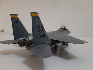
I started by assembling the landing gears. As usual in 1/72 and with models of modern planes, they are quite fiddly during assembly. After  being painted and weathered, they were attached to the model. Fit is quite tight and I ended up having a splayed main landing gears. After some trimming, they are now straight, perpendicular to the fuselage. Also, GWH moulded the main wheel tyres 'weighted'. However the instructions mis-pair the wheel halves and you might end up having a flat spot at the top of on one half of the wheel. Once the model stands on its legs, I added the weapons, pods and external tanks. I however use the Sidewinders and an AMRAAM from Hasegawa's US Aircraft Weapon Set V. The GBU-15 can easily be converted into AGM-130 simply by using adding part (which was marked as 'not used' in the instructions. If you still want have the weapon as a GBU-15, fill the holes at the bottom of the bomb. Next up is the canopy. I forgot to mention that there is a gap between the windscreen and the fuselage which needed filling. There was no problem encountered when fitting the canopy to the fuselage but by this time you realise that the tranparencies are pretty thick, especially when the canopy is in the open position. Finally the blade aerials were fitted and the build is finished.

Conclusion
The kit itself does not have any deal-breaker or any noticeable shortcomings and is a good alternative to the Hasegawa kit. The instructions however is a different matter and suffer from a number of mistakes. It probably wouldn't faze seasoned modellers but would probably cause some problems to newcomers to the hobby. Also the GWH kit, like the Hasegawa kit, only provide markings and ordnance and sensor options appropriate to the Operation Enduring Freedom / Operation Iraqi Freedom era (like clearly stated in the kit's sub-title). Aftermarket stuff were needed to to display the model in a more contemporary setting.

Friday, 13 September 2019

American Badass


Historical Background
In the late 1960s, the United States and West Germany co-operated to develop a new 'joint' main battle tank. Known as MBT-70, the programme was very ambitious and incorporated various innovations. The programme ultimately failed and cancelled by the Congress in November 1971. In its place, a new design, the XM803 was initiated but being more expensive while only having the same performance the M60, it was cancelled in December of the same year. The funds were reallocated into a new project, the XM815. The XM815 reused most of the XM803 features, but simpler and therefore less expensive. The XM815 was then redesigned XM1 and given the name Abrams after General Creighton Abrams, who become the US Army Chief of Staff in June 1972 and was considered the equal of, if not better than, the legendary Patton.


In June 1973, contracts to build the prototypes were given to Chrysler and Detroit Diesel. These were delivered in February 1976. Armed with the ubiquitous M68 gun (the licence-built Royal Ordnance L7 105mm gun), the prototypes were not only compared to each other but also the West German Leopard 2. Chrysler's prototype was powered bya turbine engine it was this design that was selected for production. Initial production was set up at the Lima Army Modification Centre in Lima, Ohio in 1979. Eleven Full-Scale Engineering Development (FSID) vehicles, still designated XM1, were produced in 1979 before the first full-production Abrams rolled out in the next year (the first FSID XM1 was given the nickname 'Thunderbolt' after General Abrams' personal mount during World War 2). In 1982, after around 1,000 M1 have been built, Chrysler was bought by General Dynamics Land Systems (GDLS). 


The M1's hull is made of solid RHA with the parts welded together. The hull front has downward-sloped 'beak' while the engine deck is raised to accommodate the turbine engine. The Abrams also incorporated composite armour inspired by the British Chobham armour. This gave the frontal turret armour of the baseline M1 an effective thickness of 350mm against APFSDS rounds and 700mm against HEAT rounds. In 1988, armour protection was improved by adding classified layers of depleted uranium and other undisclosed material. Introduced into the M1A1 model, the added material increased the effective frontal armor to 600mm against APFSDS and 1,300mm against HEAT. Interior protection against spalling is provided by a layer of kevlar. To further protect the crew from ammunition cook-off, fuel and ammo are stored in armoured compartments with blowout panels. The Abrams is also equipped with halon firefighting system and small hand-held fire extinguishers are also carried. Some Abrams, mostly seen in the USMC, are equipped AN/VLQ-6 Missile Countermeasure System that can impede the guidance system of ATGWs. 


As mentioned before, the original M1 was armed with the M68A1 105mm gun. It was getting outclassed by the then new Soviet tanks - the T-64 and T-72 by the mid-1980s . To combat newer armour technology and to increase effective range, a newer, larger gun was needed. The German Rheinmetall L/44 120mm smoothbore gun was selected to arm the M1A1 and M1A2 variants. Built under licence by Watervliet Arsenal, it entered service as M256A1. Able to fire various type of rounds as with its predecessor, the highlight of the gun was the M829 series of APFSDS rounds which were developed specifically to address the threat posed by the aforementioned Soviet-designed tanks. Secondary weapons consist of an M2 12.7mm heavy machine gun in front of the commander's hatch and two M240 7.62mm machine guns - one in front of the loader's hatch and another mounted co-axial with the main gun. 42 rounds of 120mm, 900 rounds of 12.7mm and 10,000 rounds for the 7.62mm machine guns were carried.


At the heart of the Abrams is the 1,500 hp  Lycoming (later Honeywell) AGT 1500 multi-fuel gas turbine capable of delivering 1,500 shaft horsepower. The power waqs transmitted by a six-speed (four forward, two reverse) Allison X-1100-3B hydro-kinetic automatic transmission. The Abrams is able to reach 97 km/h on road but with the engine governor in place, is limited to 72 km/h - this is mainly to prevent damage to the drivetrain and shock injuries to the crew. The multi-fuel nature of the powerplant means it can accept diesel, kerosene, petrol and jet fuel JP-4 and JP-8. For logistical reasons, JP-8 is preferred by the US military. While highly reliable, the engine is a notorious fuel guzzler, consuming 6.3 liters per mile. The engine however is quieter than a diesel and for this it received the nickname 'Whispering Death' during its first REFORGER exercise. 


The Abrams received a number of improvement packages with the most significant in the late 1990s with the introduction of the M1A2. The A2 includes improved fire control system, the commander's independent thermal viewer, weapons station, position navigation equipment and digital datalinks. Systems Improvement version One (SEPv1) provide digital maps, Linux communications and improved air conditioning. SEPv2 added Common Remotely Operated Weapons Station (CROWS / CROWS II) color displays, better interfaces, a new operating system, improved armour and upgraded transmission. To improve survivability in urban environments, the TUSK (Tank Urban Survival Kit) was initiated. Upgrades include reactive armour blocks on the tank sides and slat armour to the rear to protect against RPGs and other shaped-charge explosives. A Kongsberg RWS replaced the original, exposed commander's 12.7mm MG while a Transparent Armor Gun Shield with thermal sight was added to the loader's M240 MG. An exterior telephone allows accompanying infantry to communicate with the tank commander. The TUSK package is field-installable and 505 units were delivered by General Dynamics Land Systems. 


The Abrams entered combat during Operation desert Storm in February 1991 where it proved superior to T-55s, T-62s, Type 59s and export-version T-72s of the Iraqi Army. The long firing range of its gun outranged the Iraqi tanks, a decisive advantage in armoured warfare. Nine Abrams were destroyed during the campaign - seven through friendly fire while the other two were deliberately destroyed to prevent capture after receiving critical damage. None resulted in fatalities. Further combat took place in 2003 during Operation Iraqi Freedom. To prevent (or at least reduce) incidents of friendly fire, the Abrmas (and indeed all of the Coalition's vehicles) were fitted with Combat Identification Panels. However, as of 2005, casualties was higher with at least 80 Abrams suffered damage, 17 of them beyond repair. The majority of the damage was caused by IEDs. In operations against the Daesh in 2014, about 1/3 of 140 M1A1s of the Iraqi Army were damaged or destroyed; some were captured by the opposition. 

Today the US Army operates some 1,174 M1A2 and M1A2SEPs and 4,293 M1A1s (including variants), the USMC operates 403 M1A1while Australia have 59 M1A1 AIM, Egypt (1,200), Iraq (140), Kuwait (218) and Saudi Arabia (440). All the export tanks lack the depleted uranium layer in their armour. 


The Kit

In 2016, Meng Models joined the ranks of 1/35 Abrams model kit producers when they issued their    version of the M1A2. The second kit depicting the TUSK modifications (the first was Tamiya), the kit alllows one to build a TUSK-modified Abrams straight from the box. The box has the same footprint as the rest in the T-Rex series but deeper than usual to fit the eight sand-coloured sprues, three clear sprues, four dark brown sprues, two sheets of PE, a bunch of poly caps plus the usual decal sheet and instruction booklet. The parts are very well-moulded and have great details. There are a lot of ejector towers on the reverse side of many of the parts though  The individual-link track looks more complex to assemble than anything I have done before and should provide me with a new challenge! The kit allows two styles of TUSK: the 'straight-edge' TUSK-I or the scalloped TUSK-II ERA plates and decision has to be made early as to which markings to choose. Speaking of which, four were provided:

1. 1st Battalion, 22nd Infantry Regiment, Iraq 2008 (TUSK II)
2. E Troop, 2nd Squadron, 3rd Armored Cavalry Regiment, Iraq 2011 (TUSK I)    
3. 3rd Squadron, 2nd Armored Cavalry Regiment, Iraq 2011 (TUSK I)
4. 'Ghetto Blaster II', 68th Armored Regiment,1st Brigade, 4th Infantry Division, Iraq (TUSK I)

Construction
As usual with land vehicle kits, work started at the bottom of the hull. The foremost pair of torsion bars are of multi-part assembly and are workaable so careful application of cement is a must especially between C20/C31, C37/C38, C32/C64 and C39/C63 as the contact area is very small and to avoid accidentally gluing C29 and C36. The mud scraper was not added as it would mean extra work removing the bolt heads on the mount. The torsion bars are of the typical Meng style which can flex over diorama terrain. While the instructions have you place the wheels next, I skipped that part at this time and add the hull top first. But before the roof can be mated to the hull, the ejector towers on the reverse side of the roof have to be removed else it won't fit at all to the hull. Holes and notchess also need to be opened on the upper hull before fixing the roof and the hull together. The notches require filling as I cut them a bit too large. The engine exhaust grille is a multi-part assembly and can be posed open (when one have an aftermarket engine set that is)

Next up is assembly of the running gear. Really no problems here except for that bit of hate-love relationship I have with tank running gear in general (lots of wheels!!). Anyway, it was straightforward except that a number of the inner wheels have flash on the outside face and needed some clean-up. The tracks, as mentioned before, is a multi-part affair, and meng as usual, provided a jig to help with the assembly. I however took a totally different route. I took the DS rubber track from my Dragon M1A2 SEP (long story about why I dismantled the earlier kit). The DS is overly long for the Meng kit but a dry run shows that the excess length can be hidden behind the skirting plus, the track fit Meng's sprocket teeth. The side ERA blocks fit nicely in place although the side skirts needed a bit of 'persuasion' towards the rear of the hull.

Work on the turret was started by drilling a number of holes into the roof and also the bottom half of the turret. The position of the holes were clearly marked with indentations and arrows and 'M1A2' embossed in the plastic. The trunnion was then assembled and I noticed that despite being designed to be totally hidden by the mantlet, there are details embosssed on the trunnion. The gun was then assembled. The PE part X is meant to remain moveable and so the instructions has you taping (instead of cementing/supergluing) it to Part  D40. I eventually decided to superglue it in place after deciding to set the gun at a certain elevation. And just to be different from previous builds, the gunner's sight protective doors were posed open. meng provided different styles of armoured cables on the turret roof and the instructions need to be followed as to which version is needed for the tank you're building.

The Commander's cupola is basically a model-within-a model construction and was made separately. The periscopes (Part J1) were very tight fit and I have to sand the sides down a bit so that they are easier to fit in place. The cupola itself is a two-piece construct and there are two styles to choose (they are the same, just the way they were moulded). I however assembled just the basic cupola at this time. The shields and screens were assembled but was kept separate until after painting. The loader's shield has a gap between the panels and needed some puttying. The right-hand panel also seemed to out-of-position too, despite my effort to rectify it.

Painting and Decaling
Before the tracks were fitted onto the model, it was painted first. It was painted overall XF-1 Flat Black and after the paint has cured, the 'metal' parts of it were treated with AK Interactive Track Wash. It was then aside. I don't have the exact colour to match the modern US Sand colour so I select the next best available in my arsenal - AK Interactive AK4006 Buff Light Shade. To my eyes it looks fair enough although it is more yellow-ish and has less grey than the actual colour! Unfortunately seepage happened at one of the loader's armoured glass panel and it cannot be cleaned off as it seeped between the two already-joined clear panels! The hubs of the main wheels were painted Tamiya X-19 Smoke as these are actually translucent, which allows monitoring of the lubricating fluid inside. The whole model then received a wash using AK Interactive OIF and OEF Vehicle Wash. The periscopes / vision blocks were painted a mixture of clear colours to obtain the purplish sheen usually seen but mine ended up mainly reddish. For markings, I chose 'Ghetto Blaster II' as it was more eye-catching than the rest.

Finishing
I started by fully assembling the commander's and loader's shields and putting them in place. This was followed by the Counter Sniper / Anti-Material Mount on the mantlet. The 'grenades' for the smoke discharger were painted and then fitted in place - I used the longer ones as they were a bit easier to handle. Then accessories were added to the model using parts from the kit itself, the spares box and also Meng's own Modern US Military Individual Load-Carrying Equipment Set and Equipment For Modern US Military Vehicles set. The model did not receive much weathering (read paint chipping) as the paint on the real tank is seldom seen as such (besides, its supposed to be resistant against corrosive chemicals, what more against boot scrapes). The aerials were then put in place. Sice Meng only provides aerial bases only, the rods were made using guitar strings and for the rightmost aerial, I use the one from my Dragon M1 kit. The kit then received  a spray of flat clear. My clear parts masking however is bad and many of the armored glass panels were 'frosted' as a result. The model then recieved an overall 'dust' coverage using thinned Tamiya Buff. The lower parts of the model were then were liberally covered with MiG Production Iraqi Dust pigments. Once dried, the excess were brushed off.

Conclusion
Modellers have a number of choices to build an Abrams in 1/35. Although another Abrams may be seen to be superfluous, Meng's M1A2 TUSK is very much welcome. The details were quite sharp and yet not as complicated as other brands'. Well, I do cheated somewhat by using the tracks from my Dragon kit! It was a fun build and anyone with even those with little experience building tank kits will have no problem with this kit (the multi-part tracks may be a different matter).

Sunday, 21 May 2017

21st Century Desert Rat


Historical Background
The British FV4034 Challenger 2 was built and designed by the Vickers Defence Systems plc as a successor to the Challenger 1 MBT. The design was originally a Vickers private venture in 1986. Following the issue of a Staff Requirement for a next-generation MBT, Vickers submitted its Challenger 2 proposal to the British Ministry Of Defence (MoD), following the issue of a Staff Requirement for a next-generation tank. In January 1989, Vickers received a £90 million contract for a demonstrator vehicle. The demo phase ended in September 1990 with the tank meeting 11 key criteria for the design. This was followed by a competition from other designs, including General Dynamics' M1A2 Abrams and Leopard 2 (Improved) from Krauss-Maffei. Finally in June 1991, the Challenger 2 was declared the winner and orders for 127 MBTs and 13 driver training vehicles were placed. A further order for 259 MBTs and 9 driver training vehicles was placed in 1994. Production began in 1993 at Elswick, Tyne and Wear and Barnbow, Leeds with the first tanks delivered in July 1994.

The main armament of the Challenger 2 was the 120mm/L55 L30A1 rifled tank gun, the successor to the L11 gun arming the Challenger 1 and Chieftain. Unique among currently operating Western-designed tanks, the Challenger 2 retained the rifled barrel as the British Army continued to use the High Explosive Squash Head (HESH) rounds in addition to armour-piercing APFSDS rounds. The HESH rounds have a longer range than APFSDS and are more effective against buildings and soft-skinned vehicles. The Challenger 2 can carry up to 49 120mm rounds, usually a mix of L27A1/CHARM 3 APFSDS, L31 HESH and L34 white phosphorus rounds. The ammunition have separately bagged charge, ensuring a lower risk of ammunition explosion. The Challenger 2 was also armed with a co-axially mounted L94A1 (Hughes EX-34) 7.62mm chain gun, mounted to the left of the main armament, and a 7.62mm L37A2 GPMG mounted on a pintle on the loader's hatch ring. 4,200 rounds of 7.62 x 51mm NATO rounds were carried for the machine guns. Fire control unit was from Computing Devices Co. utilising two 32-bit processors with MIL STD1553B databus. The commander was provided with a panoramic SAGEM VS 580-10 panoramic sight allowing 360 vision in addition to the eight periscopes on the commander's station. The gunner's and commander's sight were also served by the Thales Thermal Observation and Gunnery Sight II (TOGS II), providing night vision.

For protection, Challenger 2 was clad in second generation Chobham armour known as 'Dorchester'. Details are classified but it was said that it was more than double the strength of steel. Additional explosive reactive armour blocks and bar armour can be fitted as necessary. The Challenger 2 is powered by a Perkins 26.6 liter CV12 diesel engine delivering 1,200 hp. Maximum speed was 60km/h (road) and 40km/h cross-country. Range was 450 km (road) and 250 km (cross-country). Crew was four as the British Army felt that usage of automatic loader reduces battlefield survivability (as the autoloader is actually slower than human reflexes). And unique to the British Army, the Challenger 2, like other  British Army tanks and AFVs since the Centurion, was equipped with a boiling vessel, allowing the crew to brew up tea or to re-heat their field rations within the safety of the vehicle. In 2014, some of the surviving 227 Challenger 2s are to be upgraded to Challenger Life Extension Programme (CLEP) standard. The Challenger 2 chassis was also used as the basis for other combat support vehicles such as the Titan armoured bridgelayer, Trojan Armoured Vehicle Royal Engineers (AVRE) combat engineering vehicle and Challenger Armoured Repair and Recovery Vehicle (CRARRV) armoured recovery vehicle. Although Vickers developed an export version designated Challenger 2E, it did not find overseas customers. The only export customer was Oman, which bought 38.

Challenger 2 entered service in 1998 with the 2nd Royal Tank Regiment (RTR) in Germany. Besides the 2nd RTR, it serves with the Royal Scots Dragoon Guards, the Royal Dragoon Guards, the Queen's Royal Hussars, the King's Royal Hussars and a squadron of the 1st RTR. The tank was used during peacekeeping missions such as around the Balkans but its first combat use was in 2003 during Operation Telic in Iraq. 120 Challenger 2s of the 7th Armoured Brigade, 1st Armoured Division were in action around Basra, mainly fighting against old T-55s. No Challengers were lost to enemy fire although one Challenger 2 of the Queen's Royal Lancers was destroyed in a blue-on-blue incident, being mistaken for an Iraqi tank by another Challenger from the 2nd RTR. In another incident, a Challenger was attacked by insurgents armed with machine guns and RPGs. The driver's sight was damaged and while backing away, more sights were damaged and the tank threw its track in the ditch. Now a stationary target, it was hit by 14 RPG rounds and a MILAN missile. However the most serious damage was done to the sights and it was back in action just six hours after repairs have been completed. In another incident, a Challenger 2 survived being hit by 70 RPG projectiles.  A further 'Chally 2' was damaged by RPG-29 in August 2006 and another one by IEDs in April 2007.      

The Kit
Hot on the heels of their M1A2 Abrams, Tamiya released the other main combatant during the 2003 invasion of Iraq - the British FV4034 Challenger 2 tank. The 'Desertised' in the kit title reflects the application of the full-length skirting to combat the dust of the Iraqi desert. The kit consists of 345 parts moulded in light tan plastic and 17 in clear. The quality of the moulding and detail was as usually expected of Tamiya. Also included were a small clear sheet for the commander's cupola periscopes, a sheet of thin white plastic for the turret front CIP, a length of twine for the towing cable and copper wire for the cable reel. The kit is basically based on Tamiya's earlier Challenger 1 and Challenger 1 Mk.3 kits but with suitable changes to depict a Challenger 2; the Chally 2 kit also boasted a greater level of detail on parts supposedly similar on the real Challengers 1 and 2. While many parts are well-moulded and have excellent detail, Tamiya missed the non-slip coating texture on the relevant surfaces. Also engine grill cover was not included and have to be bought separately. Decals provide markings for three Challenger 2s serving in Iraq.

Construction
As usual with AFV model kits, construction started at the bottom of the vehicle. However, Tamiya's instructions is slightly unusual by having the modeller attach the skirt mountings first. The idler mounts were not cemented to the hull but secured using the provided 1.5mm screws which allow adjustments to be made during track fitting. All the wheels were the painted while still on the sprue trees and was then cut and the scar retouched. Also out of the ordinary is the way the road wheels are placed: usually the arms were cemented to the hull first and the followed by the wheels. The Chally kit have them the other way round. The instructions also specifically orders the modeller to place the wheels rear to front. As I was not going to tempt fate, I dutifully followed the instructions! The rear panel was next where all the fittings there were cemented to it. The exceptions at his time were the rear lights brush guards and the jerry can rack. The latter was assembled but would be separate from the rear panel for the time being. The same was done to the external fuel tanks and the cable reel.

I figured that the upper hull cannot be finished without being joined to the lower half. The hull area behind the wheels (and the wheels themselves of course) were painted and the track joined. Although plastic cement can be used, I stick to cyano glue to loop the tracks. After the tracks have been fitted, the upper hull shell was slotted into place - poly caps secured the forward part of the joint. The ROMOR applique armour panels were then assembled and cemented into place. Almost all other fittings on the hull, like stowage boxes, exhausts, gun travel lock, mudguards and headlight mountings were then cemented. As the side mirrors were moulded in the stowed position, they were also cemented at this time. The fire extinguishers were not cemented at this tome to facilitate painting. Also, there are no engine grille covers provided with the kit - they are only available separately.

Work on the turret started with the assembly of the gun mantlet / TOGS fairing. The cover for the sight and an opening on the right-hand side can be posed in the opened position but I chose to have it closed. The barrel halves were joined together and as usual care has to be taken to avoid visible seams. By the way, the barrel look a bit anaemic to my eyes. It was then joined to the mantlet and set aside for a while. The turret shell was then assembled with two of the antenna bases being cemented from below the roof. The poly cap to secure the Commander's panoramic sight was also inserted. But before the turret was assembled, holes were drilled into the relevant panels in order to accommodate the CIP panels later on. While most of the clear parts were made of clear styrene, the vision blocks need to be cut from the supplied sheet of clear acetate using the template provided..sheesh! The smaller bits on the turret like the commander's sight and the loader's machine gun were assembled but set aside at this time the others were cemented. The hatches were left off as I intended to use the figures.

And now, a lesson in planning your builds : plan beforehand and only make small adjustments as you go along, not major ones unless it was unforeseen. I was referring to my decision to add the anti-slip coating sported on Challengers which Tamiya did not provide. At the start of the build, I was trying to look for methods to re-create the coating, specifically using Rust-Oleum textured paint whuch have the best texture. Unfortunately none of the local hardware stores have them and I proceeded with the build. And then I remembered I have a bottle of Tamiya Grit Effect Diorama Texture Paint. After browsing the internet, looking for ways to apply it as anti-slip coating, I summoned my courage and dived in. The effect is rather coarse and may be more suitable for the Merkava. I tried 'watering' it down by diluting the thick paint with acrylic thinner and then applying it in thin layers. The coarser bits were sanded down. As this was my first attempt, results were mixed - the turret looked rather OK while the those on the hull were coarser, resembling the coating on the Merkava. And as many of the smaller (and uncoated) parts were already on the model, clean-up work need to be done. Thankfully they can be easily scraped off using a hobby knife and/or removed using thinner.

Painting and Decalling
The Tamiya instructions call for TS-46 Light Sand as the overall colour. I felt however that that particular colour is more suited towards American vehicles and that the British modern desert colour has a more yellowish tinge to it. As it was named Light Stone, I was thinking of using the mixture used for my Grant Mk. I. The problem is that photos show bewildering shades depending on the lighting conditions but most of the time showing a darker shade than the WW2-era Light Stone. After again searching the internet, modellers mention that a more suitable mixture, taken from Osprey's Modelling The Challenger 1 and 2 book, is 3 parts XF-59 Desert Yellow to 1 part XF-3 Flat Yellow. I duly used this mixture although I added a bit more XF-2 Flat White. Even so, it still show different hues under different lighting conditions (maybe the modeller got it right then). The dust skirting was painted XF-57 Buff as many photos show them having a different colour from the vehicle itself.

As for the markings, Tamiya provided decals for three vehicles, all from the Royal Scots Dragoon Guards (Carabiniers and Greys), 7th Armoured Brigade. I am a sucker for the more colourful markings so naturally I'm attracted to Option A (Tank No.1, 2nd Troop, B Company) with a small St. Andrew's flag on either side of the turret and a Union Jack atop the TOGS. However I was more interested in the plainer, but with a lion (or is it a griffin?) crouchant of the B option (HQ Squadron, Command Troop). The model was then given a red brown pin wash to highlight details. Although many real Chally 2s suffer from flaking paints (which some modellers replicate) I decided not to add any.

Finishing
To tell the truth there aren't many things to do by this time, and mainly it was concerned with further weathering. The loader's machine gun mount was assembled and finally put in place and followed by the towing cables. Things at the rear of the hull such as the external fuel tanks and the jerry can rack were then cemented onto the model. The crew figures were painted but I deviated a bit by painting the disruptive pattern in XF-49 Khaki instead of XF-52 Flat Earth. Also, while looking at photographs, the crew helmets are mostly in a lighter colour (some are even wearing the infantry Mark 6 / Mark 7 helmets). The loader's helmet was painted XF-57 with the earphones in X-18 while the commander's helmet remain in X-18. Photographs also show that Challys carry their camouflage / thermal blanket in a U-shaped roll along the sides and the front upper glacis plate. I'm interested in adding this feature although knowing the rate I work, the putty might harden before I can add the surface features. 

After examining more photos, some show the roll being placed on the glacis plate atop the ROMOR bricks. This would have a smaller footprint, easing handling. I kneaded some two-part putty and then adding strips of Tamiya tapes and lengths of sewing threads. The still-soft putty was then pressed on the model. This resulted in elongated 'dough', the excess of which was cut. The placement was not not centred but I guess tank crews don't bother much if the roll is straight or not under combat conditions! Surface features were then added using a toothpick, a hobby knife and a nail file. Not sure about the colour of the roll, I painted it a mixture of XF-57 Buff and XF-49 Khaki. A water carton was placed between the loader's and commander's hatches while a ration carton was placed on the glacis plate (it is of the 10-person pack for infantry squads and not really suitable for a 4-person tank but what the heck). Guitar strings were cut and were then superglued to simulate radio aerials. Sand-coloured pigment powder was then applied to the lower hull and tracks.

Conclusion
After rather disappointing releases of American vehicles in the post-Cold War era (the M1A2 using the 1980s-vintage M1 kit as base and the M113A2 using the ancient 1970s M113), Tamiya released a wonderful kit of the Challenger 2. Although the lower hull is still based on their earlier Challenger 1 kit, most of the parts are new and well-moulded (case in point are the applique side armours - on the real vehicles, they are similar for both Challengers but the one in the Chally 2 kit has more detail than the earlier release). The only shortcomings with this kit are concerned with the lack of anti-slip surface and the engine deck grilles. Yet they still do not detract from the fact that this Chally is a very good kit.