Tuesday, 20 October 2015

Der Luftwaffen Panzer


Historical Background
In 1933 the then-Oberst Heinz Guderian wrote specifications of a tank tasked with dealing with other tanks (and another supporting the infantry). In January 1934 the German Army's Army Weapons Department (Waffenamt) drew plans for a medium tank weighing 24,000kg with a speed of 35km/h under the cover names Versuchkraftfahrzeug 619, Mitlerer Traktor and 3.7cm Geschutz-Panzerwagen. There was a conflict between the Waffenamt and the Inspector for Mechanized Troops about the armament. The Waffenamt was satisfied with the 37mm gun while the Mechanized Troops wanted a 50mm gun. In the interests of standardisation with the infantry, the 37mm gun was chosen. However the turret ring remain able to support the proposed 50mm weapon. Daimler-Benz, Krupp, MAN and Reheinmetall were chosen to produce prototypes, which were to be made ready by 1936. The Daimler-Benz design was eventually chosen for production. The first series, Ausfuhrung A started coming off the assembly line in May 1937. The tank was given official designation Panzerkampfwagen III with ordnance inventory designation Sd.Kfz. 141/1.

The most distinctive feature of the Panzer III and sets it apart from most of its contemporaries was the three-man turret. Allegedly influenced by the British Vickers Medium Tanks, the turret allowed the separation of jobs between the commander, gunner and loader. The commander was thus not distracted with other tasks and can fully maintain the situational awareness and commanding the tank. Since other tanks at time, such as the French Somua S35 and early versions of the T-34 did not have this feature, the German tanks had a tactical advantage in combat. This was further reinforced by the fact that the German panzers were equipped with intercom, allowing clear communications between the crew members.

The early marks of the Panzer III (Ausf. A through C) was clad in 15mm of rolled homogenous armour on all sides. This was considered insufficient and was thickened to 30mm in Ausf D to G. Ausf H had another 30mm layer while Ausf J added 50mm plate on the front and rear while the late Ausf J to M added another 20mm to the front hull and turret. The Ausf. A to early Ausf. F Panzer IIIs were armed with a 3.7cm KwK 36 L/45 gun which was adequate during the early campaigns of World War 2 but when confronted with the powerful Soviet tanks, the larger 5cm KwK 38 L/42 were fitted to Panzer III Ausf. G to early Ausf. J and finally the longer 5cm KwK 39 L/60 on late Ausf J and L. The final Ausf. N was armed with 7.5cm KwK 37 L/24 weapon (the same weapon arming early Panzer IV marks) as they were designed as support tanks. Secondary armament was two MG34 7.92mm machine guns mounted co-axially with the main gun (reduced to one after Ausf. F) and another MG34 mounted in the hull. Power was provided by a Maybach HL 108 TR petrol engine rated at 250hp which was later replaced by a Maybach HL 120 TRM rated at 300hp. The early Marks used various leaf-spring suspensions while Ausf E standardises on torsion-bar suspension.

Panzer IIIs were used in the campaigns against Poland, France, the Soviet Union and in North Africa. The early versions used in Poland were found to be vulnerable to Czech-built 47 mm anti-tank gun, Solothurn and UR anti-tank rifles and even the low-velocity 37 mm guns arming FT and R35 tanks (although at short ranges). The first real test was during Fall Gelb, the invasion of France and the Low Countries. Panzer III Ausf. E, F and G armed with 37 mm guns were all involved. The Allies however were equipped with better protected tanks, able to shrug off the 37 mm rounds. The French Char B1 and the British Matilda were impregnable to all German anti-tank weapons except the 88mm flak cannon. The German panzers eventually prevailed through better tactics, excellent communications and coordination (down to individual tank level), speed and coverage by the Luftwaffe. In the deserts of North Africa, Panzer III Ausf. F and G formed the early backbone of Rommel's Afrika Korps. They had some success against the British cruiser tanks but still failed against the Matilda. Later, late Ausf.G and H, armed with KwK 38 50 mm gun were received and towards the end of the campaign, KwK 39 L/60-armed Ausf. L and M were received. For the invasion of Russia, all Panzer IIIs have now been upgunned with the 50-mm gun. While sufficient to destroy BT fast tanks and T-26 light tank forming the bulk of Soviet armor, the gun was inadequate against the T-34 and KV tanks.

By the end of the war, the Panzer III were no longer in front line service and only a handful were present at Anzio and North-West Europe. The Panzer III chassis were selected as the basis for the Sturmgeschutz III assault gun. Apart from new-built vehicles, many Panzer III were converted into Sturmgeschutzes when they were returned to factories for overhaul. More than 5,700 Panzer IIIs were built during the war. The Ausf. L entered production in June 1942. 653 were produced by Daimler-Benz, MAN, Alkett, Henschel, Wegmann, MNH and MIAG until December of that year.


The Kit
Tamiya came up with a new-tool kit of the Panzer III in 1997. The release depicts an Ausf. L, replacing the 1960s/1970s vintage Ausf. M. The Panzer III was released alongside the Sturmgeschutz III in the same year, so the two kits share most of the chassis. The parts are spread among five dark yellow sprues, a pair of vinyl one-piece tracks, four polycaps and a decal sheet. Although the parts count are not as extensive as those found in a Dragon kit, the Tamiya offering has very good details moulded onto it. The rather glaring exception was the lack of engine deck screens, which have to be purchased separately (which I did). The vinyl tracks, although have great details, have the guide teeth moulded solid, instead of hollow as they should be. There isn't really any options when building this kit, just two styles of spaced armour for the front plate. Decals provide markings for five tanks:
1.  II01, 15th Panzer Regiment, 11th Panzer Division, Battle of Kursk July 1943 (Dark Yellow/Red Brown)
2. 02, Fallschirm-Panzer Division 'Hermann Goering', Germany 1942 (Panzer Grey)
3. 1 15, 10th Panzer Division, Tunisia 1943 (Gelbraun)
4. 200, 18th Panzer Division, Russia 1942 (Dark Yellow)
5. 133, s.H.Pz.Abt. 502, Russia 1942 (Dark Yellow/Olive Green)

There is also a couple of 'extra' decals that weren't shown in the instructions. This took the form of a skull and crossbones, which I believe is meant for probably the most notorious of the SS divisions - the 3rd SS-Panzer Division 'Totenkopf'.

Construction
The instruction follows the usual assembly sequence for an armoured vehicle in that it starts by sticking things to the lower hull. The torsion bars were cemented to the hull and attention has to be given to the details as there are two types of them and need to be put accordingly. Sticking to the Tamiya philosophy of easy to be build kits, there were only the outside structure of the suspension, unlike Dragon's Panzer III J I built before. This was followed by crew escape hatches (?) and the final drive housing; a poly-cap was inserted into each of the housing to allow movement of the sprocket wheel. Afterwards it was time for a rather tedious job assembling the road wheels; good thing the Panzer III has only six sets per side (I still curse the designer of the Panzer IV and the one who suggested that the German heavies and Panthers use the overlapping wheel arrangement). The muffler and the rear hull panel was then cemented into place. Tamiya in the 1990s-early Noughties has that annoying trait of having separate PE parts and I have to suspend the build for nearly a week, while waiting for the PE parts to come through post. 

Before assembling the upper hull, a number of holes were drilled into it in order to accommodate the lights. All the hatches and covers were then cemented on the upper hull. The hull machine gun barrel was not cemented at this time. Next up was the spaced armour plate at the front of the hull. Tamiya provided two styles but without mentioning which style goes to which marking. The second style involved some cutting; although straightforward, I chose the first style. Well you should always try to use the path with the least resistance right? More stuff were added to the upper hull but I left all the pioneer tools off. Part D27, the turret ring guard was marked as optional; again, there is no indication whether it should or should not be used in conjunction with any of the markings. The wheels were all assembled but they would only be fitted to the model after painting.

Attention was then turned towards turret assembly. The turret upper and lower halves were mated
first and all hatches, ports and sundry small parts were cemented onto it. The commander's cupola is a rather simplified affair with no periscope details. The gun, which include rudimentary breech was assembled and inserted into the mantlet. Some careful gluing was done so that the gun is still moveable. The recoil mechanism housing and the mantlet spaced armour mount were assembled and fitted to the gun. As the parts count are relatively low, the build process was rather quick and now it was time for painting.


Painting and Decaling
All the markings are interesting but after looking at my collection, I found that there were only two panzer grey vehicles in my collection: a Panzer II and a Sd.Kfz.222 armoured car. I used a mixture of 70% Tamiya XF-63 German Grey and 30 % XF-18 Medium Blue, plus roughly 20% white for scale effect. The decals were then applied. I was having second thoughts as the Hermann Goering Division's markings were rather bland, but I decided to stick with it. The tools were painted on their sprues and will be touched up later. Afterwards, I applied the sludge wash on certain parts of the model - not really appropriate for a tank model but sufficient for me to pop up some of the recessed details.

Finishing
To start the final leg, I attached all the remaining loose parts such as the pioneer tools and the aerial holder. The wooden block was painted XF-59 Desert Yellow and dry-brushed XF-64 Red Brown to simulate wood grain. I had another attack of laziness and simply paint the pioneer tools a straight XF-59 and XF-56 Metallic Grey. The exhaust and muffler were also painted XF-64. For weathering, I started by applying thinned XF-57 Buff all over the lower hull, tracks and wheel. For the lower hull, I was quite undecided whether to use 'desert' or 'European' pigments as there was no real indication as to the time frame of the tank's markings. The HG Division took part in Barbarossa and a battle group of them took part in the Battle of El Alamein. Grey paint meant a general time period before the summer of 1943. There were barely any photos of the HG prior to their participation in Sicily and Italy. So in the end I took a middle way (sort of) by mixing Mig Productions' Gulf War Sand' and "European Dust'. They mixed with water and applied liberally. The excess was then removed using a stiff brush. 

Conclusion
Tamiya has come up with another simple yet finely executed model. Assembly is hassle-free as usual, and the moulded-on details, while rather simple for some modelers, are good enough for the casual (or those not suffering from AMS) modelers. Like I mentioned elsewhere, a simple, yet detailed kit is a good antidote for stress after building a 1,000 part 'premium edition' kit!

Sunday, 4 October 2015

Storm On The Offensive


Historical Background
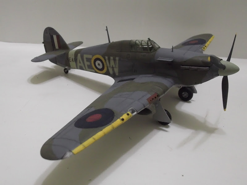
Some time in 1933, Sydney Camm, the lead designer working for Hawker Aircraft Ltd decided to design a monoplane fighter prototype, which was based on the failed Hawker P.V.3 proposal for Air Ministry F.7/30 requirement (which in turn was based on Hawker Fury fighter). The aircraft's  wing is of cantilever design, armed with four rifle-calibre machine guns and powered by a Rolls-Royce Goshawk engine.The drawings were completed in January 1934 but it failed to generate interest from the Air Ministry officials. Camm and his team went back to the drawing board and make changes which include fitting of retractable undercarriage and replacing the Goshawk engine with RR PV-12 engine, soon to be known as the legendary Merlin. In September, Camm approached the Air Ministry again with his improved design, and this time the response was more enthusiastic. In November 1934, the Air Ministry issued Specification F.5/34 which called for a eight gun-armed fighter. The design was at too advanced a stage to modify the original armament. By January 1935 a new mock-up was finished and approval has been given to build the prototype. Specification F.36/34 was written to around this design and in July of the same year the specification was amended to include an eight-gun armament. Work was completed in August 1935 and the prototype first flew on 6 November 1935. RAF trials began in February 1936 and reports from test pilots were favourable. Hawker proposed the name 'Hurricane' to the Air Ministry, which was approved in June 1936.

Despite being more advanced than the biplane RAF fighters of the time, the constructional design of the Hurricane was already outdated. It has a Warren truss box-girder primary fuselage structure with steel longerons and duralumin cross-bracing fastened mechanically. Over this basic structure, wooden formers and stringers carried the doped linen covering. The wing, while having steel spars also have doped linen covering. In April 1939, stressed-skin duraluminium wing was introduced and was used for all the later marks. The metal wing allowed a higher diving speed than the fabric-covered versions. Although many early airframes were retrofitted with the new wing, many Hurricanes still have the fabric-covered wing during the Battle of Britain. The prototype and early production aircraft was fitted with a fixed-pitch, two-bladed propeller, which was inefficient at low speeds. In April 1939, De Havilland variable-pitch propeller was used in production aircraft and was later replaced with a Rotol constant-speed propeller. The Hurricane was ordered into production in June 1936. In December 1937, it entered squadron service when four aircraft joined No.111 Squadron at RAF Norholt.

The Hurricane had its baptism of fire on 21 October 1939 when 'A' Flight of No.46 Squadron intercepted nine Heinkel He 115s which was earlier attacked by two Spitfires of No.72 Squadron. Four of the Heinkels were shot down. During the Phoney War, the French Government requested for 10 fighter squadrons to bolster the Allied strength. Air Chief Marshal Sir Hugh Dowding was concerned that the request would deplete the home defences, so he initially send only four squadrons (Nos. 1, 73, 85 and 87). They were soon joined by Nos. 607 and 605 Squadrons. In May 1940, with the German Blizkrieg erupting in the West, three further squadrons, Nos. 3, 79 and 504 were sent. During the Battle of France and Operation Dynamo, Hurricanes claimed 499 kills and 123 probables. German records, available to the Allies postwar, showed a loss of 299 aircraft destroyed and 65 damaged. Of 452 Hurricanes fighting in France, only 66 returned to the UK; 178 of the Hurricanes were abandoned at their French airfields when the squadrons were ordered to return the Home Islands. During the Battle Of Britain, from 10 July-31 October 1940, the workhorse Hurricane formed the majority of Britain's fighter defences and despite the aura and glamour of the Spitfire, actually shot down more Luftwaffe aircraft than the latter. Generally the Spitfire goes after the fighter escorts while the Hurricane concentrated against the bombers.

In North Africa, the Hurricane reigned supreme over Italian fighters such as the CR.32, CR..42, C.200 and G.50 but suffer reverses when confronted with Bf 109s and Macchi C.202 and were replaced by Curtiss Tomahawk/Kittyhawk. Back in the ETO, the the Mark IIBs with 12 machine guns  and underwing racks were used in cross-Channel raids. The additional machine guns and the bomb load of the so-called 'Hurribombers' weighed down the aircraft and restricted its performance, nevertheless, it made for excellent attack aircraft, especially when re-armed with 20mm and 40mm cannons (the latter was used in the tank-buster role). They also played a significant role in the defence of Malta. In the Far East, 51 Hurricanes were sent to Singapore but the addition of the Vokes air filter plus additional four .303 machineguns fitted made them rather unwieldy while lack of an early warning system caused many aircraft being destroyed on the ground by Japanese bombing raids. The Hurricane was later used in a fighter-bomber role.  Also, the Hurricane was modified slightly, by adding arresting hook and catapult spool to become Sea Hurricane fighters for the Royal Navy. A total of more than 14,853 Hurricanes of all marks were built.

The Kit
Hasegawa first came up with a kit of the Hurricane (a Mark IIC, with four 20mm cannons) in 1997. Kit JT66 used here depicted the Hurricane Mk. IIB (or Mark IIA Series 2). The IIB featured a Merlin XX engine with peak power output of 1,280 and was armed with either twelve .303 Brownings (eight original guns plus two in new gun bays outboard of each of the landing lights) or four 20 mm Hispano cannons. A hardpoint for ordnance and/or fuel was added under each wing. The kit first came out in 1999. The leading edge panel for the weapon is separate, featuring the four-gun opening plus holes to be drilled in order to accommodate the extra guns and the bomb rack. The parts are well-moulded, having good surface detail and judging from previous Hasegawa kits, it should be easy to assemble. As the markings include a Hurricane from the North African theatre, a two-piece Volkes filter was also included. Neither PE nor resin parts were include. The decal sheet provide markings for two aircraft: a No. 274 Squadron and a No. 402 (Canada) Squadron.

Construction
Construction, as usual, started at the cockpit. The cockpit floor, certain interior parts and the instrument panel was painted flat black while the rest of the parts were painted British Interior Green using Tamiya XF-71 Cockpit Green (IJN) as it is fairly similar to the British Interior Green, plus it saved me the hassle of mixing the Tamiya mixture I used on my previous British WW2 aircraft. The cockpit parts are fairly detailed with the proper tubular frame between the seat and the instrument panel. No seat belts are provided however. The assembled cockpit was set aside and I started building the fuselage. The fuselage was typically split vertically but Hasegawa moulded the nose section separately, so that they would only make nose moulds for the different Marks. The nose and fuselage section were mated first on the respective sides first. Holes were drilled in the nose (to fit the exhaust glare shields) as I had already chosen the No.402 Squadron option beforehand (the holes can be puttied over, should I change my mind). The cockpit was then glued to one of the fuselage sides and the fuselage was then closed. Fit wasn't terribly good though, some puttying was needed, especially on the nose.

The wing assembly was next. Before gluing the parts together, more holes were drilled in the lower wing panels for the bomb pylons and the cartridge ejector holes for the additional outer pair of machine guns. The landing gear bay and part of the forward fuselage/wing junction were then glued to the lower wing panel. And speaking of the landing gear bay, it was riddled with ejector pin marks - I left it as it is as they won't be visible to the casual observer. Holes should also be drilled into the bay as they are, on the real aircraft, windows used by the pilot to confirm retraction of the gear. The raised details on the starboard upper wing root was removed using a hobby knife as per the instructions. Although instructed to be added later in the build, I added the panels for all the wing guns. Fit wasn't good, especially for the main gun panels. The bomb pylons were also added at this time. Holes were drilled into the additional machine gun panels before cementing them to the wing's leading edge.

The upper wing panels were then cemented to the lower half. Next, the wing assembly was then cemented to the fuselage. Fit was really not good with a rather large gap at the rear of the wing-fuselage joint, perpendicular to the raised rib effect. Not only the seam line broke the rib lines, any puttying and sanding works would remove further details from the area. Good thing it's fairly out of sight! The interior of the radiator was painted and cemented and this was followed by the radiator fairing. Decision as to which markings to choose has to be finally made when finishing the front lower fuselage as the No.274 Squadron, being based in the MTO, was fitted with the Vokes filter. I chose the No.402 option and used the regular chin fairing. This also meant the the exhaust glare shields have to fitted.

Painting and Decalling
RAF tactical aircraft in Europe after 1941 were painted Medium Sea Grey (bottom) and a camouflage pattern of Ocean Grey and Dark Green. The paints I used for the colours are Tamiya XF-83 (Medium Sea Grey) and XF-81 (Dark Green). I do not have XF-82 in stock, yet I am not in a mood to mix XF-24 Dark Grey, XF-21 Sky and XF-18 Medium Blue. IPMS Stockholm suggested that XF-54 is a good match for Ocean Grey and that's what I use, although I modify it a bit by adding XF-18 Medium Blue. The ID band on the leading edge and propeller blade tips were painted XF-3 Flat Yellow. The prop spinner was painted XF-21 Sky while the blades were painted Flat Black. The wheel bay and landing gear were painted Tamiya XF-11 (I had run out of Gunze 8). The decals were then applied the usual way. There was a bit of silvering for the squadron code letters (because of the raised ribs on the rear fuselage), even though decal softener has been applied. I waited until the decals are safe to touch, get a sharp blade, make cuts at the affected areas and reapply Mr. Mark Softer. I also punched holes in the decals over the machine gun openings.  

Finishing
What's left is to finally fix the still-loose parts. The landing gear was assembled, the paint retouched and cemented to their places, allowing the kit to stand on its own. The exhaust was painted Burnt Iron and then cemented. This was followed by the rest of the more vulnerable parts, although I left the boarding stirrup off (the stirrup is not visible in many photos of the Hurricane, so I assume it was retractable and hence, it was not attached here). I almost forgot about the outboard guns and I placed the pieces-of-plastic-pretending-to-be-gun muzzles to their places. I then applied sludge wash on the model. The bombs were then finally fixed in place. The model then received a spray of flat clear and once the paint has cured, the masks were removed, finishing the build.

Conclusion
The Hasegawa Hurricane is typical of their offering with the good points of clear instructions and generally good detail and fit. The bad points are not-so-detailed interior, no seatbelts (even in decal form) and some fit issues; and particularly for Hasegawa's Hurricanes, the joint across the fabric effect at the bottom of the wing-fuselage junction. Oh, and thick decals too. But otherwise it was actually an easy build, you just need to have that little bit of patience. It was for years the best 1/48 Hurricane(s) in town until Italeri and Airfix came up with their offering a few years back.

Saturday, 19 September 2015

The One Who Kills Tanks


Historical Background
When the Lockheed AH-56 Cheyenne attack helicopter was cancelled in 1972, the US Army began its search for an anti-armour/attack aircraft that would still be under their command.  As the 1948 Key West Agreement forbade the Army from operating fixed-wing aircraft, its next attack/anti-armour aircraft would have to be another helicopter, but one with better performance, firepower and range than the AH-1 Cobra. Also needed is sufficient agility to allow nap-of-the-earth flying. On 15 November 1972, the US Army issued a Request For Proposal for an Advanced Attack Helicopter (AAH). Proposals were submitted by Bell, Sikorsky, Hughes, Lockheed and Boeing Vertol/Grumman. In July 1973, the US Department of Defense selected Hughes' and Bell's proposals as finalists. Each company build a prototype for a fly-off : Bell with Model 409/YAH-63 and Hughes with Model 77/YAH-64. After evaluating the test results, Hughes' YAH-64 was selected as the winner. Reasons for YAH-64's selection include more damage-resistant four-bladed rotor of the YAH-64 and the instability of YAH-63's tricycle landing gear arrangement. The AAH program then entered Phase 2 where three pre-production AH-64 would be built, plus the two YAH-64 flying prototypes (and a static ground test unit) would be brought to the same standard. The airframes would be used to test weapons and sensor systems, including the new AGM-114 Hellfire (Helicopter-Launched, Fire and Forget) missile.

In 1981, the pre-production AH-64As  were delivered to the Army for further operational tests. They were successful but the Army decided to upgrade the engines (General Electric T700 turboshaft engine) to the more powerful Dash 701 version. In late 1981, the AH-64 was named the Apache, keeping with the US Army's tradition of naming its aircraft after American Indian tribes. In 1983, the first production Apache rolled off the Hughes Helicopters at Mesa, Arizona with the US Army formally accepting it in January 1984. In the same year, Hughes Helicopters was bought by McDonnell Douglas. The 7th Battalion, 17th Cavalry Brigade became the first operational Apache unit when it began training with the AH-64A in 1986. 

The Apache's configuration followed the arrangement first used on the AH-1 by having the two crew members sitting in tandem with the co-pilot/gunner in front and the pilot behind and above him. Both are however capable of flying the helicopter and performing weapons engagement separately. There is a shielding between the cockpits, so that at least one crew member can survive hits. The cockpit compartment (and also the rotor blades) are designed to sustain a hit from 23mm rounds. In total, some 2,500 lb of armour protected the airframe and the fuel system is of the self-sealing type. The airframe was also strengthened to meet the crashworthiness requirements of MIL-STD-1290. The original AH-64A was powered by two General Electric T700-GE-701 rated at 1,696 shp each driving a four-bladed main rotor and a four-bladed tail rotor.

A Hughes (now Alliant Techsystems) M230 30mm Chain Gun formed the Apache's permanent weapon system. The M230 can fire up to 625 rounds per minute. The Apache can carry 1,200 rounds of ammunition but usage of the so-called 'Robby tank' reduces this capacity to 300. The weapon-carrying configurations of the Apache are highly customisable for the roles assigned to it. The most common weapons carried by the Apache are Hydra 70 general-purpose 70mm unguided rockets, usually carried in 19-shot M261 rocket launchers. The most significant weapon however is the AGM-114 Hellfire missile. Originally developed for anti-armour use, later version of the Hellfire can be used for other target types, including individuals. In late 1980s, the Apache was also evaluated to carry AIM-9 Sidewinder and FIM-92 Stinger air-to-air weapons and also the AGM-122 Sidearm anti-radiation missile. The Apache crew is provided with the Integrated Head And Display Sighting System (IHADDS) which, among others, allow the crew (any one of them) to slave the Chain Gun to their helmet, making the gun track to wherever the crew member is looking. The gun can also be controlled via the Target Acquisition and Designation System (TADS), or locked to fire ahead. The TADS is also part of the TADS/PNVS (TADS/Pilot Night Vision System). Other systems also include GPS and passive IR countermeasures.

Apart from the US Army, the Apache was used by Egypt, Greece, Indonesia, Israel, Japan, Kuwait, Netherlands, Saudi Arabia, Singapore, South Korea, Taiwan, UAE and United Kingdom (who licence-build the AH-64 as AgustaWestland Apache). The Apache was first used in combat during Operation Just Cause in 1989. In the next year, nearly half of the US Army's Apache was deployed to Saudi Arabia for following the Iraqi invasion of Kuwait. On 17 January 1991 around 0210L, Task Force Normandy, consisting of eight Apaches led by two USAF MH-53J Pave Low III, fired the first shots of Operation Desert Storm when it destroyed Iraqi radar stations near the Saudi/Iraq border which could have warned Bahgdad of the upcoming attack. A total of 277 Apaches took part in Desert Storm, destroying 278 tanks and numerous APC and other vehicles. One Apache was lost to ground fire, when it was shot by a RPG at close range. 

The Apache was then sent to the Balkans during the conflicts in Bosnia and Kosovo, The deployment was a failure for the Apaches as none were flown in combat missions due to fears of casualties. Problems faced include deficiencies in training, night vision equipment, fuel tanks and survivability. One Apache crashed during training in Albania on 27 April 1999. In Afghanistan, for Operation Enduring Freedom and in Iraq for Operation Iraqi Freedom, The D-model Apaches often remove their Longbow radar due to lack of armoured threats. In Iraq, an Apache was downed by in a flak trap on 24 March 2003 for which the then-Iraqi government attribute the downing to a farmer armed with a rifle (he denied it later). The Apache was captured intact, although it was destroyed by an airstrike the next day. By the end of US operations in Iraq in December 2011, several Apaches  had been shot down or lost in accidents. Apart from the US Army, the Apache was also used by its other users in combat.

The Kit
The Hasegawa kit dated from 1983 and the particular boxing I use here is a 2008 re-release, featuring new parts. The kit, as with many other Hasegawa kits feature nicely engraved details but lack the rather prominent rivet details . The rotor head while having a correct shape, lacked details. There aren't much option for the weapons load - just the basic two FFAR pods and 16 Hellfire missiles (at least Hasegawa helicopter kits come more or less fully armed cf. their aircraft kits). The decal sheet provide markings for an AH-64 from the 3rd Battalion, 227th Army Aviation Regiment. Also included is a 'numbers jungle' so that any AH-64As can be built.

Construction
I have an unbuilt Italeri Apache in my stash. It suffered an awful accident, resulting in a broken fuselage and decided to keep the best bits to be used when I finally have the Hasegawa version. Anyway, as usual, the build starts at the cockpit. As with many 1/72 scale cockpit, the detail is sparse with all the instrument faces, switches and dials in decal form. The entire cockpit was painted XF-1 Flat Black and I didn't bother with dry-brushing or washes as there are no raised or recessed details to speak of. I originally wanted to replace the kit's seats with the Italeri ones, but I felt that the side armour plates of the latter are overscale. Although not mentioned, the cushions (or, as it is, just the seat back) were painted XF-62 Olive Drab. Before mating the fuselage halves, the cockpit sidewalls were painted Flat Black and the cockpit tub cemented to one side. I was thinking of making the rotor moveable but in the end decided to fix the shaft in place. I found that the ALQ-144 IRCM 'disco ball' has no details so I cut it off and have replaced with the one from the Italeri kit.

Although the next step is concerned with the engine pods, I skipped that step for a while and add the bottom of the fuselage first. To ease painting and assembly, the main landing gear and the Chain Gun were left off. The tail plane was also cemented although the tail wheel was left off, again to avoid accidental breakage. After that I returned to the engine pods. Each engine pod consists of three parts, plus two-piece exhausts. The parts fit nicely but I only dry fit the exhaust assembly at this time, again because of painting considerations. The canopy, which have the pilot's access panel moulded separately (so that it can be posed open), was cemented, with the separate panel in the closed position. I however neglected to check the fit, resulting the panel being slightly off. Looking at the TADS/PNVS turret, the Italeri one has sharper detail and substituted the former with the latter. Finally the stub wings are attached to the fuselage. The pylons were however left off at first. The rocket pods and the Hellfire missile racks were also assembled at this time, but remain separated.

Painting and Decalling
US Army helicopters are painted the so-called 'Helo Drab' although nearly all of the instructions for so many US Army chopper kits called for Olive Drab. As far as I know, only Testors' Model Master brand have Helo Drab in their range but I could not find any. Online searching also turned up nothing about Tamiya mixes to get this colour. Photos on the internet show a bewildering shade: being greyish, olive-ish or brown-ish, depending on the camera angle! In the end I decided to make a custom mix, using just the eye to judge the 'accuracy'. I mixed Tamiya XF-51 Khaki Drab with XF-62 Olive Drab until I get the approximate colour (it may still be the wrong shade!) and paint the model. The sensor apertures were painted X-18 Semi-Gloss Black and /or Gold.  The canopy sealant are not painted as I do not own a small enough brush for that purpose. As for markings, since there is effectively only one marking set, I applied the decals according to the instructions. I may be wrong, but the Italeri "United States Army" title looks better and I use them. The decals were then set in place using Mr Mark Softer.

Finishing
I started by assembling the landing gears, so that the model can stand on its own. Afterwards, the pylons were cemented onto the stub wings. The Hellfire missiles and Hydra rocket pods were painted straight Olive Drab, while the seeker portion was painted silver (I should have dabbed just a bit of silver as the seeker window is pretty small. Afterwards the ordnance were loaded onto the model: the Hellfires were cemented to the launch rails before the assembly was cemented to the stub wing. The rocket pods, being placed outboard, were the last. The Chain Gun was pretty simplified, so I added a bit more parts using plastic rod and fuse wire. The assembly was then slotted into the lower fuselage. The exhaust assembly was then cemented. Finally the main rotors were assembled. I however replaced the kit rotor assembly with the Italeri one as the latter has better detail (then again the detail may be wrong for an Apache!). In any case, the rotor blades in both kits are moulded without the droop (when idle). To add the droop, I soaked the blades in hot water and then carefully bend them downwards. It might not match photos but at least the blades are now droopy. The mast is the last item cemented although somewhat inexplicably, I used the Hasegawa rather then the Italeri counterpart. Sludge wash was then applied to enhance the panel lines.

Conclusion
The Hasegawa kit of the Apache, even though dated from the 1980s can still hold its own against its market rivals. The fit is good with well-detailed parts (of course there are certain exceptions) and the ugliness of the design was well captured by Hasegawa. The details can be improved, if one wished, by using aftermarket parts but what comes in the box are enough satisfy the average modeller.


Friday, 18 September 2015

Support For The Scouts


Historical Background
The Associated Equipment Company (AEC) of Southall, Middlesex was set up in 1912 and became well-known for its trucks and buses, especially the famous London double-deckers. With the outbreak of World War 2 in 1939, the company was geared for war, producing the 10-ton, 4-wheeled Matador artillery tractor (a 6x6 version was also produced, named the Marshall but was always referred to as a Matador). In 1941, a private-venture move was made by AEC to produce a multi-mission armoured car for the British Army using the 4x4 Matador chassis. The prototype was shown to officials at the Horse Guards Parade in London 1941. Winston Churchill was impressed and ordered the vehicle into production.

The AEC Armoured Car was fairly large as the designers intended it to be a 'wheeled tank', being cheaper and thus being able to be produced in larger quantities than the real tank. The vehicle utilised the Matador chassis, including its engine and transmission and thus able to carry heavier armament than its contemporaries. Size-wise, it's impressive, having a long and tall structure and a narrow, lozenge-shaped armoured body. The driver sits at the front with the fighting compartment in the middle. Despite the rather narrow aspect of the body, the fighting compartment was roomier than the one of the Valentine tank. Large stowage boxes were placed between the mudguards, also creating a step for the crew to mount their vehicle. The frontal armour was 65mm thick but sloped angle increased the effective thickness to 90mm, with side armour being 13mm thick. This protection came at the cost however with the vehicle weighing 11 tons. However production vehicles were powered by the AEC 190 diesel engine rated at 105hp and giving a power-to-weight ratio of 9.5hp per ton for the Mark I. This in turn gave the armoured car a speed of 65 km/h and range of 400km, sufficient for most long-range reconnaissance missions.

The first production version, the Mark I was armed with a 2-pounder gun and a co-axial BESA 7.92mm machinegun. The turret the same as those fitted on Valentine Mark I/III infantry tank. The Mark II had a different turret and were armed with a Ordnance QF 6-pounder gun and the BESA machinegun. This version was heavier, at 12.7 tons. To cope with the heavier weight, the engine was changed to AEC 195 (158hp). The final Mark III was armed with a Ordnance QF 75-mm gun. An AA variant armed with a Crusader AA turret was built but was not ordered into production. Tactically, the AEC was used to support other armoured cars in the reconnaissance regiment. It saw first action during the North African campaign in 1942 by the British and the Indian Armies. They later saw service in Italy and North-West Europe, where they were supplemented by the American-built Staghounds. The AEC gave good service, which was reflected in its usage by the British Army well into the 1950s when it was eventually replaced by the Saladin. The AEC was also bought by Lebanon, who used them until 1976.

The Kit
Miniart came up with the kit of the AEC in 2013, releasing all three versions in the same year. The Mark III kit was comprised of 534 light gray parts, 50 brass PE parts and eight clear plastic parts. There is a substantial number of parts related to the interior. They are definitely needed if you want to pose all the hatches in the open position. Of particular note are the 75-mm rounds as they need to be shortened to allow fitment into the ammo racks - a rather tedious job as there are around 40 of them! Again the steps in the instructions can be skipped if you chose to have your model buttoned up. Also included is a pair of Vickers K machineguns, to be mounted on the turret roof (although all the pics I have seen show that the AEC was not equipped with them). Also, be aware of tiny parts - both PE and plastic - there are lots of them! A driver figure in driving pose is also included. The decal sheet provide markings for three vehicles:

1. F 88886, Royal Armoured Corps Gunnery School, Lulworth Camp, Dorset 1944
2. F 88707, Heavy Troop, D Squadron, 2nd Household Regiment, VIII Corps, Normandy June 1944
3. F 89007, 1st King's Dragoon Guards, XII Corps, 2nd British Army, North-West Europe, Spring 1945

Construction
After browsing the instruction sheet, I believe I can skipped about 1/3 of the assembly process as I intended to have my AEC buttoned up (except for the turret).I totally skipped Steps 1-4 and only added the external parts to the side walls in steps 6 and 10. The engine bulkhead was also left bare. Although Miniart included a driver's figure, I decided not to use him for this model and therefore the driver's compartment was also left bare.The side walls, bulkhead and the driver and fighting compartment floors were then cemented together. Steps 16-21 are concerned with the undercarriage. I am of the opinion that the basic chassis is a bit over-engineered as the 'thingies' that hold the leaf spring suspensions should be moulded together with the frame, rather than separately. Also the front leaf springs are not symmetrical but the actual placement was not shown in the diagram...so I made a guess and hope that I was right. Part Ba5 is also not symmetrical and the assembly sheet should be looked at closely.

The rear suspension however have ends corresponding with their mountings so it wasn't a problem here. The gear box was assembled and cemented in its location. However while the position was quite clearly marked in the instructions, it wasn't really so on the plastic. The engine was then assembled but I only use the larger parts only. Anyway when dry-fitting the engine, I found that the connection between the engine and the gear box fell short. I guess it was my mistake rather than Miniart's. However, since the engine and the gear box is mainly out of general view, I left them as they were. Up next were the axles, there were no problems here except that if you put Part Ba5 (mentioned earlier) incorrectly, you will find that the front axle won't fit properly into the suspension. The front brakes however are loose and need to be glued to the axles.

Moving to the upper hull, the driver's hatch was cemented to the upper hull/roof. It has to be done prior to cementing the roof to the hull as it was easier to do it that way. As I intended to have the driver's hatch in the closed position, none of the details were added underneath the hatch door. The mountings for the windshield is downright tiny and I nearly lost them! For the rear part of the upper hull, Step 51 really had to be done first and the assembled parts put in place. This is in order to avoid misplacing Part F12 which, if placed incorrectly, will create a larger gap so that part E41 cannot be cemented between the forward plate and Part F12. Once this was done, the engine hatch covers can be put in place. The storage boxes on the sides were assembled and cemented into place. Afterwards, things stuck on the front mudguards like the headlight, brush guard and the towing eyes were cemented and the mudguard was then cemented to the hull. The rear mudguards were next. I cemented Parts E4 and E5 to the hull first and the cemented the main mudguard structure to them and the storage boxes as there no positive locating pins for the mudguard.

Next up is the turret. I started at the front face by assembling the internal gun mantlet, the Besa machine gun and the breech end of the main gun. As I intended to have the turret hatches closed, I forego doing the interior. The turret walls was then mated together, along with the bottom. The one-piece roof and the rear wall were next but the one in my kit was a bit warped. I soaked it in hot water, gently 'massaging' it back into shape. It was then cemented to the turret shell without problems. The details on the turret was then attached but certain items, like the lifting eyes on the either the turret sides were left off (the third one at the back was cemented at this time - these eyes were delicate, no need to guess what happened!). Sometimes a compromise had to be taken, such as the mounting for the turret stowage box. I do not own a 'proper' PE bending tool so I have to use a piece of plastic to maintain the spacing between the stowage box and the turret's rear face. The main gun has rather short pins (and the recess is shallow on the turret face) for effective surface mating so I have to use superglue for this part. Care also have to be exercised here as the the pin/recess is not keyed and I have to make sure the muzzle brake is properly aligned. I also decided not to use the roof-mounted twin Vickers K machineguns.

Painting And Decalling
I intended to paint the model using Mike Starmer's mix of SCC15 Olive Drab; however I have run out of 'proper' (so to speak) Olive Drab. I decided to improvise by using 7 portion of the 'wrong' batch of Tamiya XF-62 Olive Drab, 3 portions of XF-3 Flat Yellow and a dash each of XF-64 Red Brown and XF-61 Dark Green plus flat white for scale effect. The test mix look close enough and painting commenced. For markings, I chose the second option, that is, an AEC III of the 2nd Household Regiment. The markings however only provide the Arms of Service and unit markings for the front only. Perhaps Miniart did this to maintain 'photo-accuracy' but I believe the set of markings fo the rear should be included (by the way. the third option only have markings for the rear). The decals received the Mr Mark Softer treatment but the silvering persisted for some of them. Pin wash was then applied to selected areas.

Finishing
Finishing work starts by attaching the more vulnerable parts and/or parts painted mainly in a different colour than the main body. The radio aerial at the back of the turret is a two-part affair, with plastic base and a PE part. Due to its fragility (because it's so thin), the PE part was distorted during assembly and attempts to make it as round as it should be resulted in further distortion, so I have to leave it like that. Also, the lifting eyes of the turret suffered from being knocked around during the handling of the turret. The Bren Gun included in the kit (to be hanged outside the turret) was painted and put in place. I glued a piece of kitchen aluminium foil to act as reflecting surface of the rear-view mirror and then sementing the assembly to the mudguards. However, the mounting is to be glued butt-joint to the mudguard; because of the cylindrical shape of the pole and the mount, it can fit properly. I have to cut a small 'channel' on the mount so that the assembly can be more secure whilst drying.

The outside was pretty bare so I decided to add a 75-mm ammo box from Academy, a rolled tarp from Tamiya and a pair of 4-gallon flimsies from Bronco. However I have gotten tired of this kit (despite all the shortcuts) by this time and decided to let the stowage be put in place by 'magic' (i.e not adding tie-downs and straps)...or perhaps the crew has yet to stow them properly...haha. Finally, Mig Productions European Dust pigment was mixed with water and applied under the mudguards, the lower hull and the tyres. Once dry, the excess was removed using a stiff brush, and in the case of the tyres, were partly removed using enamel thinner. As there are no tabs to secure the turret, a slab of plasticene was placed underneath the turret basket to provide friction and also acting as some sort of 'holder' for the turret. Finally, Miniart provided just two tow cable shackles and the builder has to provide his own cable. The leftover twine from previous kits are too big for the shackles, so I just have to leave this rather essential piece of equipment from the model.

Conclusion
Again, the Eastern European (and the newer Far Eastern companies) are more ambitious than the more established companies in introducing kits previously not available (or having only limited availability). And in the case of the AEC armoured car, not only Miniart produces kits for all the major variants, they also throw basically everything a modeler wish for a basic vehicle - including full interior. This resulted in a rather long build but I believe the end justifies all that work. Sure, I skipped many of the construction steps as I do not intend to build up the interior and having them disappear from view. Even so, it took up some of the longest time I took to build a 1/35 AFV kit. Actually it has more to do with holiday breaks and losing some of my modelling mojo rather than actual difficulty with the kit.

Tuesday, 8 September 2015

Italian Cavalry Scout


Historical Background
In 1938, the Italian Royal Army (Regio Esercito), issued a request for a new armoured car to replace the Lancia IZM, basically a souped-up version of the 1918-vintage Lancia-Ansaldo cars. The IZM was however underpowered and had poor off-road capability. Ansaldo-Fossati came up with a four-wheel drive, four-wheel armoured car concept. The new vehicle need to fulfil the requirement for a fast and versatile car for colonial policing and and the army's cavalry. Production soon started in 1940 and the vehicle was given the designation Autoblinda 40, or AB 40. The main features of the AB 40 include all-riveted hull with sloped armour, rear-mounted engine and twin machineguns in a turret. The wheels can have the tyres removed and the car be used on rails. The two spare tyres were hanged in the way so that they can rotate freely and help in navigating rough terrain. The four-wheel drive, while revolutionary, was however quite troublesome. The AB 40 was however produced in small quantity: just 25. They were used during the Italian 'invasion' of southern France in June 1940 and afterwards they were sent to Libya.

In the Fall of 1940 however, a new requirement was issued. A modified version of the AB 40 was required, equipped with a 20mm Breda modello 35 autocannon. The easiest solution was to replace the original turret with the turret from the L6/40 light tank. Tests of the prototype was promising and the AB 40 on the production line was replaced with this version, dubbed AB 41 (after the year of first production, 1941).  Apart from the 20mm cannon, the AB 41 was armed with a co-axial 8mm Breda modello 38 machinegun. Another Breda 38 (a carryover from the AB 40) was retained on the rear of the crew compartment. A total of 456 20mm and 1,992 8mm rounds were carried. With the additional weight of the turret, a more powerful Fiat SPA ABM 6-cylinder petrol engine was needed. Rated at 120hp, the new engine allowed the Ab 41 to maintain a top speed of over 70km/h and the higher torque also offered better off-road capability. Range was a respectable 250 miles. The complicated drive system provided six forward and four reverse gears and to fully exploit the latter, a second driver was placed at the rear of the crew compartment (also a carryover from the AB 40). All AB 41s were equipped with radio and a long aerial, making them useful scout vehicles. Armour was also good (15mm for the front plate). The vehicle was not without flaws however, chiefly the one-man turret, unprotected fuel tank and the lack of interior bulkhead, making life unbearable for the crews in North Africa.

The AB 41 was used in all theatres of war in which Italian troops took part: North Africa, the Balkans, Eastern Front and the Italian homeland. They were issued to cavalry, Bersaglieri and the Polizia dell'Africa Italiana (Italian African Police). Like the AB 40, the AB 41 can be converted for railway patrol duty using a conversion kit, resulting in the Ferrovaria (railroad) version. The Ferrovaria was especially useful in the Balkans where the partisans were actively resisting the Axis occupiers. Following the Italian Armistice in September 1943, 57 AB 41s were confiscated by the Germans who renamed them Panzerspahwagen AB41 201(i). There are only two vehicles derived from the AB 41. The AS 42 Sahariana was basically a turretless AB 41 and developed for operations in hot and dry (read North Africa) combat conditions. Another version was the AB 43, armed with a  47mm Canone da 47/32 M35 anti-tank gun. Just 12 of the latter were produced before the armistice. Another 120 were built for the Germans. In total, 550 AB 41s were built.

The Kit
Despite being the most important Italian armoured car during World War 2, the AB 41 was not kitted by a mainstream manufacturer until 2005 when Italeri announced their kit. The kit comprised of 140 parts in tan-coloured plastic plus six rubber tyres. The usual decal sheet and instructions are there but no PE parts are included. However like Tamiya kits, the Italeri AB 41 has enough details to satisfy the average modeller. The details are well-moulded and I am very pleased with the embossed details on the side wall of the tyres. However, while all the doors and hatches can be posed open, there is no interior detail. The painting instructions are in colour and separate from the assembly instructions. The kit provide markings for five vehicles, including two German vehicles for those who won't build anything without a Black Cross (even the box art shows the German option!):

1. German Army, Aufkl.Abt.236, 162nd (Turkische) Infantry Division, Italy, early 1944
2. German Army, I./Elite-Polizei regiment, Bolzano, Italy, Summer 1944
3. Regio Esercito, Unknown unit, Sicily 1943
4. Regio Esercito, Lancireri di Montebello Regt, Rome, September 1943
5. Repubblica Sociale, Gruppe Corazzato Leonessa, Torino, Italy, early 1945

Construction
The build started at the chassis and Italeri provided a rather simple affair which consists of a horizontal 'pan', two sides and the ends. There are just small lips to align the parts but in the end, two u-shaped parts stabilises the joint. Next up were the suspension and steering mechanism. They are simpler than most other kits but care has to be taken since parts B8 and B9 have a tight fit and might snap if one is not careful (I end up enlarging the holes). More parts for the suspension were added to the kit. Again Fit of Parts B13 and B14 is fairly tight. To ease handling, Parts B15 and B16 were cemented directly to the chassis, rather than cementing them to Parts B13 and B14 first. This proved to be a blessing as it allows me to adjust the parts with Parts B18 and B20 (the brake drums). Should they be cemented as instructed, the brake drums might not fit properly. The suspension was finished by adding the drive shafts. While there is a notch at each wheel end of the assembly for positive placement, there were none for inside the chassis. The best way to fit this is by cementing the wheel ends and align the ends inside the chassis.

The hull of the kit was made up of multiple panels, rather than a basic shell onto which smaller panels are attached. First parts C22 and C24 are cemented to their respective sides of the walls. As the separate panels may lead to alignment issues, Italeri provided four cylindrical stiffeners, to be placed between the walls. These add some rigidity while building up the hull. However the locating pins are slightly too long and need to be trimmed. The bottom rear hull panel was then cemented. Before assembling the rest of the hull panels, the rear-facing machinegun was fitted into the upper rear panel; the design of the parts allow the machine gun to swivel freely in its place. There is a bit of fit problem between Parts 30C and 31C but a quick sanding work eliminated the problem. The rest of the panels did not have good fit but the open bottom made for some flexibility, allowing the joints mated better through finger pressure. For those who want to show off the headlights, you will be disappointed with this kit as the lenses and glasses are solid ( I simply place the covers in the closed position). There are a number of ejector pin marks but they are mostly at the wheel arches (all six of them) and are judged to be mostly hidden, so I left them as they were. 

Work on the turret was started by assembling the main armament. The breech end of the gun and also the machine gun is fairly simple but not really an issue as I'm going to close off all the hatches. The muzzle of the gun is separate and require care when cementing it to avoid seams. Apart from the machine gun and the main gun (and the telescopic sight), there isn't anything much inside the turret. There is a turret traverse wheel but since the turret hatch would be closed, I didn't put it in place. The wheels remain separate from the body and the tyres were not fitted to the wheels at this time. It's off to the paint shed.

Painting And Decalling

Italeri, like Tamiya, has a rather annoying habit (depending on your POV, really) of having only their paints in the colour callouts. Checking on instruction sheets available online, I painted the model a basic layer of 2:1 Tamiya XF-60 Dark Yellow and XF-59 Desert Yellow plus 20% white for scale effect. Afterwards it was time to decide which markings to use. The German vehicles were rejected out of hand, leaving the Italians. The 'Black Shirt' vehicle is simple, without camouflage patterns but para-military organisations are not really my cup of tea. That left the the two Army vehicles. I finally chose the Sicily-based vehicle as the pattern is less confusing than the other. The green is painted using a 60/40 mix of XF-65 Field Grey and XF-58 Olive Green while XF-64 Red Brown was used for the brown. Aftwerwards, the decals were applied and as usual the decals perform flawlessly. A thin layer of XF-57 Buff was then applied all over the model to 'tie-up' the colours.

Finishing
The smaller parts can now be fixed to the model. Due to some rather clumsy cutting, I clipped off the lower part of one of the horns; I however have run out of putty and reluctantly have to leave it as it is. Another clumsy handling resulted in one of the width indicator snapping off, and again, the carpet monster quickly grabbed it as it hit the floor. Replacing one meant replacing both of the indicators. Using the surviving piece as a guide, I cut 0.5mm plastic rod to size, drill a hole in each of the indicator bases and use leftover balls from a Legend Productions Merkava III update set. It look smaller than the original but perhaps it is more to scale. The pioneer tools were painted and fixed onto their places Finally the exhaust, after being painted Burnt Iron was fitted. Pin wash was then applied. The wheels and tyres were assembled and afterwards, I applied Tamiya Weathering Master Sand all over the wheels. Once completed, the wheels were mounted on the model.

Conclusion
Despite a number of issues (admittedly they are minor), the AB 41 kit has good enough details overall. Italeri are also to be commended for producing a model of a vehicle many mainstream manufacturers ignore - because of the lack of Black Crosses and unpronouncable names (even Tamiya, who has a licensing agreement with Italeri, only adopt the follow-on AB 43 kit, as the vehicle was almost exclusively used by the Germans!). The simple construction makes it very attractive and I believe there is a number of aftermarket goodies that can be used to spruce up this kit.