Tuesday 27 October 2020

High Flyer


Historical Background
In January 1939 the Soviet VVS issued a specification for a high-altitude fighter with inline engine. The aircraft, initially designated I-200 was designed by the Polikarpov Design Bureau. When Nikolay Polikarpov fell out of favour with Stalin, the Soviet authorities created a new Experimental Construction Section headed by Artem Mikoyan and Mikhail Gurevich. Further work on the I-200 was assigned to the two and were later recognised as its designers. Now known as the MiG-1, the aircraft was designed using wood and steel tubings to minimise the usage of light alloys. It had some serious defects however, including inadequate visibility while taxiing, heavy controls, poor longitudinal stability and easily entering into an unrecoverable spin. Continual improvements were done throughout the production run but were not immediately implemented on the production line. Instead, they were incorporated into the fourth prototype. After testing and passing State acceptance trials, they were incorporated in the 101st I-200/MiG-1 built and the aircraft was now renamed MiG-3. The first MiG-3 was completed on 20 December 1940.

The changes however resulted in an aircraft over 250 kg heavier than the MiG-1, which reduced maneuverability and field performance. Despite that, the MiG-3 can fly at 640 km/h at 7,200 meters - faster than the Bf 109F-2. However speed decayed to 505 km/h at sea level while the 'Friedrich' could do 515 km/h. Unfortunately the low and medium levels were where most aerial combat took place on the Eastern Front where the MiG lost its speed advantage. The loaded weight of the MiG was also higher than the Bf 109 and it was less maneuverable due to its higher wing loading. Despite being designed as a high-altitude fighter, it has poor climb rate. Aerial gunnery was also difficult because of instability at high speeds. Standard armament consists of a single UBS 12.7 mm machine gun and two 7.62 mm ShKAS machine guns. Considered underpowered, 821 aircraft were then fitted with a 12.7 mm UBK machibe gun pod under each wing - this further lowered the speed by 20 km/h at all altitudes. Some pilots decided to remove the extra weapons. Other aircraft were armed with just the ShKAS machine guns but were fitted to carry RS-82 rockets.

On 22 June 1941, most of the MiG-3s delivered to the V-VS were placed within the Leningrad, Baltic, Western, Kiev and Odessa Military Districts. These aircraft fought at a disadvantage as combat took place at medium and low altitudes. Plus, shortage of ground attack aircraft forced it into that role, for which it was totally unsuited. By the time of the commencement of Operation Taifun, most V-VS MiGs were transferred to the PVO where their lack of performance at low altitude was not so serious. Even so, none of the MiGs remain with the PVO by January 1945. 3,400 units of the aircraft were built. Production was terminated in 1942 following Stalin's telegram to the directors of Zavod N.1 demanding increased production of Il-2 Shturmoviks. Despite its bad reputation aces such as Aleksandr Pokryshkin scored their early victories while flying the MiG-3. 

The Kit
Trumpeter was (and still is) a very profilic producer of model kits especially in the period between the mid-noughties until mid-2010s. They first came up with a model of the MiG-3 in 1/48 scale, an 'Early Version' of the MiG-3 in 2007. This was followed by the 'Late Version' in 2008. The 82 parts are spread among five sprues, one of them in clear plastic. Surface detail is generally nice and crisp although the fabric representation on the control surfaces look exaggerated. The infamous Trumpeter rivet is not as prominent in this (cf. their 1/72 Thud kit) - probably because of the larger scale. The interior is quite OK although the tubular frame is moulded-on with the side walls. Details on the instrument panel is somewhat ambiguous at the bottom of it. The front fuselage is made up of four parts and I suspect some struggle during assembly (more on that later). The decals provide markings for three aircraft:
- Winter-camouflaged 'Black 7' with 'For Stalin!' slogan. This aircraft was shown with additional guns in nacelles underneath the wings but the relevant parts are not included in the kit;
- 'White 12' in green with black nose; and
- 'White 95' in two-tone green.

Construction
As usual with aircraft kits, work started at the cockpit. And as per my usual style, the parts were painted while still on the tree. While Trumpeter has GSI H70 (RLM02) as the interior colour (and for the entirety of the cockpit), I chose to paint it blue-grey using a mix of Tamiya XF-22 RLM Grey and X-14 Sky Blue. The instrument panel is supposedly entirely in black but I chose to have just the instrument faces in that colour. The side boxes and some details were also painted Flat Black. The radio rack was also painted and assembled. The tail wheel was glued into place before closing the up the fuselage - otherwise it will be impossible to do so with the fuselage halves mated. Guess what? The lower half did not want to meet, leaving quite a sizeable gap which need to be addressed with putty. The placement of the radio deck in the instructions is very misleading and might confuse a modeller (it should be behind the pilot's seat, not inside the canopy fairing!).

The wing assembly is next. The upper and lower wing halves were cemented without fuss. The inserts for the wing root intakes fit OK with the rest of the wing although I suspect some fiddly handling during the mating of the wing assembly with the fuselage. The wing was then mated to the fuselage - it was a very tight fit but a bit of wedging here and there allowed the wings in place. As expected, some filling was needed between the intake insert and the wing root. The rear of the wing assembly also need to be in line with the corresponding surface on the rear fuselage as there were no hook or projection whatsoever to secure the two areas. Because of its position, the radiator faces and the intake and exhaust areas were painted first before assembly. The upper nose fairing did not fit exactly with the main assembly - but that's Okay as apparently many of the real aircraft have the same characteristics!

Painting and Decalling
After deciding to do 'Black 7', I proceeded to paint the lower fuselage first. Trumpeter suggested Gunze H20 Light Blue - a colour which I don't have in hand. To approximate AII Light Blue, I used Tamiya XF-23 Light Blue and gradually add XF-8 Flat Blue until looks about right. The upper fuselage need to be painted a base colour first, for the white camo to stick. I used XF-5 Flat Green. masking material was applied to the wing roots, weapon troughs and the leading edge of the wings before the upper fuselage was sprayed Tamiya TS-27 Flat White. The diagonal red patch at the wing tips were painted a mix of Vallejo Flat Red and Flat yellow to approximate the recommended Insignia Red. The decals were then applied. They are thin and lie nicely upon the surface. They are however translucent and this showed up like a sore thumb when the fuselage red stars were laid on the black arrow flash. To reduce the discrepancy, I trimmed numbers 9 and 5 from the red stars for option 3 of the markings and applied them over the original stars.

Finishing
The masking material was removed and the border between the white and the underlying green were cleaned / messed up further using dots of XF-2 Flat White and XF-5 Green. The model then received a neutral wash using Mr. Weathering Color Multi Grey. Pin wash was done using further application of the same some for the white areas and Ak Interactive paneliner for the lower fuselage. Exhaust marks were added using Tamiya Weathering Master Soot. The more fragile parts, such as the radio aerial, the rocket launchers, the main landing gear, tail wheel covers, propeller and the pitot tube were then cemented into place. Oh at this time, I realised that the main landing gear doors were scale-thick and the portion stuck with the gears were way simplified.. The model then was sprayed with Gunze Flat Top Coat. The masking for the clear pasrts were then removed, finishing the build.

Conclusion
While Trumpeter's MiG-3 kit is well moulded,and engineered, it was not a Tamiya, There wasn't really a problem with the build - you just need a bit of experience and this kit was not exactly suitable for entry-level modellers. The one particular unnecessary over-engineering is the radiator air intake - causing gaps if built according to instructions and fiddly to adjust if you add them after mating the wings to the fuselage. Fit was also slightly off with the kit, especially between the upper fuselage panel and the windscreen and the upper panel with the main fuselage. Nevertheless, overall, it is a good kit and should present no big challenge to seasoned modellers.


Monday 21 September 2020

TIE In The Sky


Fictional / Real-World Background

To replace Republic- and early Galactic Empire-era starfighters, the Imperial Navy ordered the new TIE starfighters from Sienar Fleet Systems. The mass-production TIE/Ln fighter took its designation from the Twin Ion Engine propulsion employed by the craft. The engine utilised microparticle accelerators to agitate ionised gases to relativistic velocities. The engine also featured ion stream deflector manifolds for pinpoint maneuvering accuracy. The stream of particles gave the engines a distinct 'howl' which became one of the hallmarks of the TIE series of starfighters. However in order to reduce the mass  and energy consumption, hyperdrive system, shielding and life-support systems were removed from the design, making the craft more vulnerable to even micrometeorite strikes. 


While a good space superiority fighter, the TIE/Ln's performance fell in planetary atmosphere. The Imperial Navy then decided to build a small number of experimental fighters derived from the basic TIE design. These were known as the TIE/sk x1 air superority fighter or TIE/sk atmospheric fighter or simply as TIE Striker. The craft is a more streamlined version of the TIE Fighter and was specialised for in-atmosphere missions. Due to it's speciality, it was one of the rarest version of the TIE. The Striker feature horizontal and pointed wings designed for atmospheric combat. The wing also helped improve the TIE/sk's VTOL performance. Additional speed can be gained by curling down the wing which is also the craft's attack mode. The TIE Striker is armed with two pairs of Sienar L-s9.3 laser cannons and a pair of H-s1 heavy laser cannons which can take out enemy starfighters or medium transports with just a few shots. An unknown number of VL61-79 proton bombs are dispensed through a  chute underneath the fuselage for ground support missions and is effective against vehicles while also dealing heavy damage over a fairly large area. 

Although intended to be an atmospheric fighter, the TIE Striker can still be used in space, accompanying the standard TIE Fighters. It is also useful to transfer personnel and supplies from orbit to planetary surface due to its larger pod/fuselage. By the time the Galactic Civil War erupted, the TIE/sk was used to defend important Imperial bases, most notably the Imperial security complex on Scarif. TIE Strikers remain in use throughout the conflict. The Imperial Admiralty however frowned upon the TIE/sk, seeing it as a result of indecision and wasteful expenditure such as atmospheric streamlining, pressurised life support and ground support weaponry. Its pilots however were anamoured by such novelty.
-----------------------------------------------------------------------------------------------------------------------------

The TIE Striker was a new design developed for 'Rogue One : A Star Wars Story', the first of 'anthology' series of Star Wars movies as the movie has scenes of in-atmosphere dogfighting at the planet Scarif.

The Kit
Following the release of Rogue One : A Star Wars Story, Bandai came up with the then-latest member of the TIE family in 2017. Size-wise, it was roughly a bit longer than the Rebel Y-Wing Fighter. The well-engraved parts are spread among five sprues including two in Bandai's distinctive multi-coloured sprue - one sprue in grey and black and the other in grey, black and green. Also included are the frames-only canopies and viewscreen. As with previous kits, the TIE Striker kit can be build-up without cement. The wing panel, like on the TIE Fighter kit, is trapped between the outer frames. A display stand is included by I'm not sure whether it's stable enough for this kit. A cut-out of an Imperial TIE Fighter pilot is also included  Markings are of the usual stickers and waterslide variety and there is also the usual 'laser bolts', 

Construction
As usual with flying things, even fictional ones, construction started at the cockpit. The interior was painted FS36375 Light Ghost Grey although I didn't bother with washes as the interior would be nearly invisible with the roof in place. Stickers were used for interior detailing. The hand-less pilot was also unpainted although decals were used for the Imperial insignia on the helmet. The cockpit interior halves were then mated together. This was followed by assembling the fuselage proper. The snap-tight construction means that there was actually no need to dab cement on the joints but a bit was needed on the forward portion to seal a slight gap. The TIE Striker is a two-seat craft although Bandai didn't bother with the rear cockpit as nothing could be seen anyway through the clear openings in the canopy. Some smaller parts were attached (and cemented, just in case) and the fuselage was set aside. The wing assembly is left off until after painting. I however forgot to paint the area under the rear canopy black. While not really visible from the outside, the empty interior is quite plain to see under a strong light source!

Painting and Decalling
Using my previous builds of Imperial TIE Fighters as a guide, the TIE Striker was Tamiya TS-32 Haze Gray. Unlike other Imperial TIE designs, the viewscreen frames and some small parts of the fuselage were painted Flat Black. The wing solar panels were painted Vallejo Anthracite Grey. The display stand was unpainted. Some small decals were then applied.

Finishing
The I started with the wing assembly. Nothing to shout here with the wings themselves as they fit very well. It was however quite a tight fit for the completed wing assembly to fit into its slot on the fuselage. The model was then given a wash. By this time, I am quite confident that the model can receive the enamel wash treatment and stuff from AK Interactive was used. The model then received a final coat of semi-gloss clear paint. It was then mounted on the display base. And talk about the latter, while it was basically the same as others in the series, it was just flat, plain plastic. Bandai however instructed the modeler to place the plinth in the opposite direction to ensure balance.

Conclusion
As with just about other Bandai's Star Wars model kits, the TIE Striker is a snap to build (pun, more or less, intended). There were not many parts and painting was straightforward (just two colours effectively) and not much weathering. Again, like building other TIE Fighters, you can even skip painting the interior as the cockpit is a virtual black hole and can hardly be seen from the outside especially if the clear plastic viewport and top hatch were used (the frame-only equivalent actually makes it easier to peer inside!).

Wednesday 2 September 2020

"Kucing Laut"


Historical Background
In the 1960s, the British Army issued a requirement for improved helicopters. As the French Army also had the same requirements, Westland Helicopters and Aerospatiale signed an agreement in early 1967 to jointly develop the helicopter for their countries' armed forces. While Aerospatiale became the design leader for the large helicopter (eventually emerged as the Puma) and the 'small' helicopter (which became the Gazelle), Westland took up the development of the medium helicopter, initially known as WG.13 (and later as the Lynx). The first prototype of the Lynx flew on 21 March 1971. In 1972 a Lynx broke the world speed record over 15 km and 25 km by flying at 321.74 km/h and then set a new record for 100 km closed circuit by flying at 318.504 km/h. The British Army put an order for more than 100 Lynx AH.1 to perform various roles including transport, armed escort, anti-tank, reconnaissance and evacuation. Deliveries began in 1977

Meanwhile, the Royal Navy found that the Westland Wasp inadequate and had a strong interest in the Lynx. Therefore a navalised variant was developed as Lynx HAS.2. While the naval HAS.2 retained the twin Rolls-Royce Gem turboshaft engine of the Army Lynx, it differed by having fixed tricycle landing gear, foldable main rotor and tailboom, deck capture and and restraint system, emergency floating system and a bigger nose containng a Ferranti Seaspray radar. The colloquially-named Sea Lynx first flew on 10 February 1976 and officially entered service in 1981. The HAS.2 was then upgraded to HAS.3 with the addition of a towed magnetic anomaly detector, uprated transmission, Gem Mk 204 engines and Orange Crop ESM. In 1984, an enhanced version called Lynx-3 was proposed but was not pursued with due to insufficient orders. However in the early 1990s, Westland incorporated some of the Lynx-3 technology into a less radical design called the Super Lynx. This variant featured BERP rotor blades, new tail rotoer (derived from WG.30 design), a new under-nose 360-degree coverage radar, Gem 42 engines and optional EO turret in the nose. Royal Navy Lynx HAS.3s upgraded to Super Lynx standard were known as HMA.8. The Super Lynx was also offered to prospective clients as upgrades to their existing fleet or as new-build craft.

In order to fulfil maritime patrol, anti-submarine, anti-surface and SAR duties, the Royal Malaysian Navy placed an order for six Super Lynx Series 300 in September 1999. These would also complement the then newly-delivered Lekiu-class frigates. The RMN Mk.100 Super Lynx is powered by a pair of LHTEC CTS800-4N turboshaft engines rated at 1,563 shaft horsepower. It also incorporated an all-new glass cockpit with active LCD displays and new avionics. Half of the fleet is equipped with EO sensor on the nose. The pilots are also provided with NVGs for night-time operations. Anti-submarine weaponry consists of two A-244/S lightweight torpedo while anti shipping vessel weapons consists of up to four (but usually just one or two) BAe Sea Skua missiles. Pintle-mounted FN MAG 7.62 mm or FN M3M 12.7 mm machine gun may also be be fitted. The Lynxes are grouped into No.501 Squadron and was land-based at KD Rajawali.

The Kit
Hobby Boss came up with a bunch of Sea Lynxes in 2009. The HAS.2 version was the first release, followed by HAS.3, Super Lynx, Sea Lynx Mk.88 and Sea Lynx Mk.90. For this build, I chose kit No. 87239 (Lynx Mk 88). All the kits generally have nicely engraved and raised details although most details for the cabin interior is missing save for some equipment boxes and jump seats (which I think were usually not installed in the naval Lynx). The model is also missing the pedestal-mounted winch for SAR work. The nose is separate so that modelers can chose either to have the radar nose of the one with the EO sensor dome. There are also two styles of main gear fairing so chose according to your reference. For external ordnance, two styles of torpedoes (a pair each) and a pair of Sea Skua missiles are included. Decals provide markings for two Bundesmarine birds.

I however intended to build a RMN bird and so have purchased a conversion set from Naza Model Works. This set includes a new engine fairing, exhausts, the aforementioned winch, a new instrument panel, central console and also a small decal sheet.

Construction
As usual, the construction steps started with the interior of the aircraft. However, this time I started by sawing off all the resin replacement parts off their pour stubs and hacking away portions off the main fuselage halves. The NMA conversion kit did not actually show the areas to be removed but their FB page shows a post of the conversion part being dry-fitted to the basic kit and that indirectly shows which area of the original kit to be removed. Only then did I continue with the interior. There wasn't much to do here as the kit's interior is quite sparse (there wasn't even the collective stick!). The troop seats can be left off as the Super Lynx (at least in those in Malaysian service) were rarely used as troop transports. I just add the seat behind the pilot for the cabin interior. The holes on the cockpit floor were then puttied in. However, the base for the rotor shaft cannot be used as the replacement engine housing is too thick at the opening for the rotor shaft and cannot be drilled through easily. 

Next, the replacement engine fairing is put in place. But before that, holes for the exhaust were cut out (the resin is thin over the openings). The resin wafer covering the air intakes can be left on (and painted black later on) or removed although the latter option means they open into nothingness (not really a problem actually). Since I cut badly, extra putty were needed to cover the gaps between the fuselage and the engine housing. There are two types of sponsons provided and the one similar to RMN Lynxes' were used. However the chosen sponsons lacked some detail such as tie down eyelets. As RMN Lynxes have both radar and EO noses, decision has to be made here and it was, more or less, dictated by the provided decal sheet. The latter only provide markings for M501-1, -3 and -5 which have EO sensor on the nose

Although the conversion kit includes the winch assembly, I didn't use it as I have the cabin doors closed. The ESM antennas on the rear of the fuselage was not fitted on RMN Lynxes and the holes were puttied in. The blobs on the mount were removed and transplanted to rear of the sponsons. Obliterated cabin door railings were restored using styrene strips (one looks rather OK, the other, quite bad!). To ease handling while painting and decalling, the landing gears, weapons pylon and the rotors were left off at this time. Oh yeah, one more thing, part of the landing gear sponson is actually covered in canvas, so I have to mask, apply putty and sand before painting.

Painting and Decalling
I have to confess: despite my year of dabbling in scale modelling, I still can't correctly identify which colour to be used without being told which is which. In this case, I'm not sure whether the helicopter is painted in medium Sea Grey or Dark Sea Grey (despite being in front of it). Fortunately, there is a photo of the pre-delivery M501-1 in front of a Royal Navy Merlin. I know for sure that RN's Merlins were painted MSG (the instructions for an aftermarket decal sheet said so(!)) and as the Lynx looks darker than the Merlin....then it must be painted in DSG then. The area around the engine intakes, the anti-glare panel and the ESM antennas were painted Flat Black. For markings, both inbox and the conversion kit were used with the inbox decals providing most of the stencils. However, there are some 'misses' with the in-box decals. First, the port 'rescue' arrow has a different orientation than the one on the real aircraft. Secondly, a number of decals are missing from the decal sheet - there are only two decals for the kick-in steps and there is only one stripe decal for the Sea Skua missile.

Decal application went without a hitch, except for a warning sign on the starboard engine casing; the carrier film was quite stiff and somehow unable to stick to the surface. I replaced it with paint but being unable to replicate the stencil, I just painted dots to replace the alphabets...haha. Having looked into my spares box for suitable replacements, the port 'rescue' arrow had to be placed into wrong position. Another inaccurate decals are the 'Step' markers on the main wheel sponsons. And finally I decided to paint the warning stripes on the tail rotor rather than using the decals. 

Finishing
I started by adding the EO dome and the missile rack. Speaking of the latter, Hobby Boss instructed you to use Parts D5 and D6 which somehow look dubious and not used on RMN Lynxes and I believe is for the carriage of two missiles each. I decided to replace it with Parts F3 and F4 as the missile pylon can fit onto it. Test fitting however showed that the missile would be lower than the landing gear. This required further modification by removing the upper part of the pylon. On the real aircraft, there is a cable running through the antenna blades at the bottom of the tail but I decided not to add them. The main landing gears were canted outboard a bit as the real aircraft is usually seen as such (unless the wheels are chocked). The panel lines were then applied with AK Interactive Paneliner. The missiles were cemented to the pylons and the rotors were put in place.  After that the whole model was sprayed with Mr Color Semi-Gloss Top Coat, the masks removed, finishing the build.

Conclusion
Hobby Boss's Lynx is a fairly nice representation of the real thing in 1/72 scale. The outside surfaces are fairly detailed although the interior, especially the main cabin is very sparse although with all doors closed, it wasn't a problem. The decal is also quite disappointing as Hobby Boss missed quite a number of the more prominent ones especially for the kick-in steps. As for the conversion set, NMA has come up with another excellent conversion set for Malaysian armed forces'birds. My complaint against the set was just the lack of cabin machine gun mount. Although the Lynx kits from Hobby Boss are modular, and basically the same among the HMA.8, Super Lynx and Lynx Marks 88 and 90, I finally realise why NMA recommended the Mk 90 as the basic kit for the conversion - the Mk 90 kit 'essential information' decals are more appropriate for a RMN Super Lynx!  


Sunday 14 June 2020

Back To Front Hunter


Historical Background
Early in World War 2, the British Army was keen to upgrade their anti-tank capabilities. This was realised by the introduction of the 6-pounder anti-tank gun. The authorities however realised that this weapon would soon be outclassed by better German panzers and as a result,  the even more powerful 17-pounder gun was put into service. Entering service as a towed artillery piece, it was a heavy and cumbersome weapon to be moved around quickly. Therefore, a decision was made in the middle of 1942 to mount the weapon on a tracked chassis. Initially, it was proposed that the Bishop self-propelled howitzer be used as a basis. It came to nothing as the Bishop used the Crusader cruiser tank chassis which lacked adequate armour. In the end, the Valentine tank was chosen as although it was an obsolescent design, it was still in production and also quite large to accommodate the large 17-pounder gun.

With the chassis chosen, work on the project can begin. By March 1943, two pilot vehicles were completed; and since the hull of the Valentine was not big enough to support the gun in a revolving turret, the gun was mounted on a simple, low and open-topped armoured box. One of the pilot vehicles however has its gun mounted facing to the rear. For the next two months the two prototypes were put through their paces and eventually the unorthodox rear-facing mount was chosen because it made the overall length of the vehicle shorter and apparently held a tactical advantage of firing at a pursuing enemy while the vehicle is being driven away. To speed up assembly, the new vehicle, dubbed the Archer (or formally as the SP 17-pounder, Valentine), used as much components as existing Valentine tanks.

In general the Archer resembled the German panzerjagers by having a fixed casemate. It was sloped, open-topped (exposing the crew to the elements and battlefields hazards such as exploding bombs and shells) and multi-faceted . The gun shield is separate and allowed a traverse of 11° and elevation between -7.5° to +15°. 39 rounds of 17-pounder ammo were carried. While the rear-facing armament also confer some balance, the breech recoiled quite close to the driver's head who either had to exit the vehicle immediately upon reaching firing position (to avoid risking decapitation) or remain in place so that the vehicle can be re-sited at a moment's notice. Crew consisted of four persons (driver, commander, gunner and loader).

Although the prototype was ready in April 1943 and trials began immediately, production was slow to start due to issues that needed to be addressed. A total of 800 vehicles was ordered but the in only entered service in October 1944. By that time other 17-pounder armed vehicles such as the Achilles, Sherman Firefly and the Challenger have entered service and the order was reduced to 655 vehicles. As the Archer was designated a self-propelled gun, it was operated by the Royal Artillery (along with the Achilles). As the Allies were on the offensive by that time in the war, the Archer was more used to provide fire support and secure the flanks against counterattacks. The Archer remained in use with the British Army of the Rhine (BAOR) until mid-1950s. Some 200 were sold to Egypt post-war and saw action during the Suez Crisis in 1956.

The Kit
While the basic Valentine tank in 1/35 has been offered by various kit manufacturers over the years, its derivatives such as the Archer did not receive the same kind of attention. Accurate Armour of Scotland came up with a resin kit in 1996 and was followed by an unlicensed plastic copy by Maquette of Russia in 2002. Bronco came up with their kit in 2011. While welcome, this is one of those high-hundreds parts kits with tiny PE parts galore which are not to everyone's taste. Last year, Tamiya came up with their version of the Archer. Expected to be based on Tamiya's own Valentine kit, the Archer only shares the link-and-length track with the Valentine while the rest of the parts are entirely new. Unusually for Tamiya, all the wheels are to be cemented in place instead of the use of poly caps. The small decal shet provide markings for two Archers : a Canadian from the 3rd Canadian Infantry Division, North-West Europe and a Polish gun from the 2nd Polish Corps in Italy.

Construction
While construction for most AFV kits were started at the suspension or driving parts, the Archer kit starts with the lower hull. This was however of the separate panels variety and not Tamiya's usual 'tub' style. The driver's compartment was built up and painted although I didn't add any weathering for the more obscured areas. The separate hull panels were matched up and there was no risk of an asymmetrical hull as the parts fit snugly.  Some basic parts for the fighting compartment were next - they mainly consists of ammo racks, panelling and the engine firewall. The suspension was next. They are pretty straightforward (after all, it's simpler in construction). However, do take note the orientation of the bogies on the hull as you might mix them up. The link-and-length tracks is easy to install but you have to take not the placement of the single-piece upper run. Also, the I found that the track run is one link less than required in the diagram.

Construction then moved back to the fighting compartment. The upper hull was first affixed to the lower hull and then the gun carriage was assembled. The carriage was designed so that it is glued to the floor of the compartment while the upper part is clicked into place so that it can swivel like the real thing. Other stuff in the lower half of the fighting compartment was assembled and was the entire lower  half was painted. The splinter shields were then cleaned up, painted first and the stuff set on tthem were cemented afterwards. Some weathering on the interior was also done at this time. A decision also has to be made here as marking option A has a tube affixed on the front (or was it rear?) splinter shield. To avoid mishandlings, the aerial base (Part D38) was left off at this time.

Finally, construction moved back to the exterior. However there aren't much to do at this juncture - just the gun barrel, some storage boxes and the exhaust. The last-mentioned was assembled but not fixed to the hull at this time. The gun is a one-pieve affair with two-piece muzzle break. The joint between the muzzle half definitely needed clean-up while the barrel needed a light sanding to remove the quite visible mould seams. The gun shield/mantlet is a two-piece assembly and to ease matching it to the gun carriage, the top half (Part B3) was left off. Once the glue has cured, Part B3 can be added.

Painting and Decalling
Tamiya have you paint the model XF-61 Dark Green but I believe the actual colour is SCC 15 Olive Drab. I used Mark Starmer's formula for it. However, due to lack od a certain paint in my stock, I have to revert to his older mix of  5 parts XF-61, 2 parts XF-62 and 2 parts XF-3. And, as mentioned before, the interior parts were painted while still on the sprue and were then touched-up after assembly. The tracks were painted a base of Ak Interactive Track Base and were then washed with an application of AK Interactive track wash. The exhaust were given a base of Mr. Color Burnt Iron, a random application of XF-64 Red Brown and and a final layer of Tamiya Weathering master Rust. As for markings, I chose the Canadian option. The decals went on without any problems. Afterwards, the model received a basic wash.

Finishing
Post-painting, the weren't much to do at this point as most of the parts were already affixed in place. The exhaust were assembled and added to the model - the portions have quite a tight fit and a bit fiddly during assembly. The towing cables and the v-shaped thingie were put in place and that's about it. I however decided not to add the figures (just their helmets though) but instead I added flimsies from the Bronco British Field Accessories Set and a couple of ammunition boxes from Bronco 17-Pounder Ammunition Set. Further weathering work was done on the lower hull - mainly adding mud from Vallejo and Wilder and adding Fresh Mud Wash from AK Interactive. Weathering Pencils, also from AK Interactive were also used to add dirt and rain streaks on the model. A length of guitar string was used to replicate the radio aerial. There should be two of them but I just made one. A final coat of Flat Clear finishes the build.

Conclusion
There aren't many model kit manufacturers offering the Archer and I am grateful that Tamiya was one of those who did. Although there are omissions and some parts were simplified, what was there in the box is perfectly adequate, especially for casual or new modellers. Now, on the heels of their M10 and Achilles kits, I hope Tamiya will come up with a model of the M36 tank destroyer.

Wednesday 6 May 2020

The Mudhen Returns To Mideast


Historical Background
The F-X fighter programme which resulted in the McDonnell Douglas F-15 Eagle was specifically tailored for air superiority mission with little consideration for air to ground missions (hence the phrase 'not a pound for air to ground'). The opposition by the F-15 Special Project Office in The Pentagon caused McDonnell Douglas to quietly work on the interdiction version of the Eagle envisioning it as a replacement for the F-111, the (then) remaining Phantoms and to augment existing Eagles. In 1978, the USAF initiated the Tactical All-Weather Requirement Study (TAWRS) which, amomng others, looked at McDonnell Douglas's proposal. The study recommended that the Eagle as the USAF's future strike platform and in 1979, McDonnell Douglas and Hughes teamed up to develop the F-15's air-to-ground capabilities. An F-15B, serial number 71-0291 was modified to act as a demonstrator and was first displayed at the Farnborough Air Show in 1980.

In March 1981, the USAF announced the Enhanced Tactical Fighter (later renamed Dual-Role Fighter) programme to procure a replacement for the F-111. The programme envisioned an aircraft capable of flying deep air interdiction missions without additional electronic support and fighter escort. McDonnell Douglas submitted its now-named F-15E while General Dynamics submitted the F-16XL. After a lengthy evaluation programme, the F-15E was chosen as the winner on 24 February 1984. Key factors in the selection of the F-15E over the F-16XL include lower development costs, belief that the F-15E had future growth potential and twin-engine redundancy. The first officially-completed F-15E was first flown on 31 March 1987 and the first production aircraft was delivered to the 405th Tactical Training Wing at Luke AFB, Arizona in April 1988. The USAF contracted for a total of 400 F-15Es (later revised to 392).

The F-15E Strike Eagle, although optimized for air-to-ground missions, retains the full air-to-air combat capabilities of the original Eagle. Although the prototype was basically a modified F-15B, production F-15Es have significant structural changes and using much more powerful engines (originally Pratt & Whitney F100-PW-220 rated at 105.7 kN with afterburner, later the Dash 229 version rated at129.7 kN with afterburner). The rear cockpit position is 'missionised' to allow the WSO to work the air-to-ground avionics (while still having flight controls, allowing the WSO to pilot the aircraft should it become necessary). Conformal Fuel Tanks (CFTs), containing 2,800 liters of fuel (in addition to the original  internal tankage) on either sides of the fuselage gave the Strike Eagle its long legs at a slight cost in drag and performance. The APG-70 radar system incorporates Doppler Beam Sharpening, Mapping and Synthetic Aperture Radar modes to enhance operational capabilities. One feature of the system is that it can 'freeze' the air-to-ground radar map and then goes back to air-to-air mode to check for aerial threats. In addition, the WSO is able to designate ground targets while the pilot engages aerial targets. The APG-70 was replaced by the APG-82 AESA radar beginning in 2014.

The F-15E carries most air-to-ground weaponry in the USAF inventory, from 'dumb' Mk 80 series bombs to precision strike JDAMs. Since it inherits the original Eagle's counter-air capabilities, they regularly carry air-to-air missiles and trained for counter-air missions. Precision delivery of weapons by day or at night and in poor weather was made possible by the use of LANTIRN pods mounted externally. The targeting pod (AN/AAQ-14, AN/AAQ-28 LITENING or AN/AAQ-33 Sniper Advanced Targeting Pod) contains a laser designator that can mark an enemy's position from as far away as 16 kilometers. The AN/AAQ-13 navigation pod  contains a terrain-following radar to allow the aircraft to fly safely at very low altitude and it even allows a hands-off terrain-following capability. The pod also contains a FLIR for night or low-visibility flight conditions. Tactical Electronic Warfare System (TEWS) integrates all the countermeasures available (RWR, chaff, flare, radar jammer). An AN/ALQ-131 ECM pod can be carried if required.

The F-15E, dubbed Strike Eagle (or more popularly, the Beagle ('bomb eagle') or Mud Hen) achieved initial operational capability on 30 September 1989 with the 336th Tactical Fighter Squadron of the 4th Tactical Fighter Wing at Seymour-Johnson AFB, North Carolina. The Strike Eagles were first deployed for combat during Operation Desert Storm conducting diverse targets, from mobile Scud missile launchers to fortified bunkers. They were also involved in 'tank plinking' attack missions prior to the start of the Coalition's ground offensive. An air-to-air 'kill' was scored on 14 February 1991, when an F-15E hit a flying/hovering Mil Mi-24 with a GBU-10 laser-guided bomb. USAF F-15Es continue to be deployed in various operations such as during Operations Northern & Southern Watch, Operation Deny Flight, Operation Enduring Freedom, Operation Iraqi Freedom, Operation Odyssey Dawn and Operation Inherent Resolve.

The Strike Eagle also enjoyed export success with variants being sold to Israel (F-15I Ra'am), South Korea (F-15K Slam Eagle), Saudi Arabia (F-15S/SA) , Singapore (F-15SG) and Qatar (F-15QA). Proposed variants include F-15SE Silent Eagle incorporating internal weapons carriage and use of radar-absorbent materials. Israel and Saudi Arabia have also used their Beagles in combat.

The Kit
Despite being in service since 1989, the F-15E received a rather cool attention from model kit companies. The 1/48 fraternity is quite well served with a number of kits depicting the E version but the 1/72 community was less so with the prototype-feature kit from Hasegawa (who then, true their policy, re-released it a number of times). The same goes with Airfix, Academy and Italeri. In 2011, Fujimi came up with a new-tool Beagle. While having all the 'E' features, it unfortunately suffered by being overscale, something around 1/66 rather than 1/72. In 2012, Hasegawa finally decided to do a new-tool F-15E in 1/72 scale. And now we have a relative newcomer, Great Wall Hobbies with their rendition and I think this kit is a worthy rival to the Hasegawa kit. First impression is good with parts displaying crisp recessed lines and nice (for 1/72 and in plastic) raised details. Unlike Hasegawa the GWH offering has a more contemporary ordnance to be hung beneath the model. Decals provide markings for three aircraft:
1. 87-0173 'Shark Mouth', 391st Fighter Squadron 'Bold Tigers', 366th Fighter Wing, Mountain Home AFB, 2002
2. 87-0169 'Tiger Lead', 391st Fighter Squadron 'Bold Tigers', 366th Fighter Wing, Mountain Home AFB, 2002
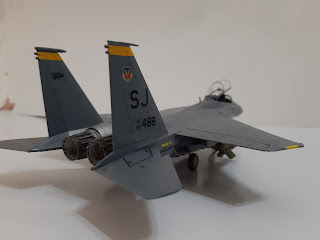
3. 89-0488 ' 336th Fighter Squadron 'Rocketeers', 4th Fighter Wing, Al-Udeid AB, Qatar 2003.

Construction
As usual with aircraft kits, construction started at the cockpit. The seats while having better details than kit-supplied parts of yore, still cannot compete against resin aftermarket ones. nevertheless I still used them for this build.  The cockpit features nice raised details, which although not mentioned, must be sanded off if one wants to use the decals for the instrument panels. I just applied them over the riased details. Also, GWH forgot to mention in their instructions about two further decals that needed to be placed for the WSO's office  And, as per my usual style, the parts for the cockpit were painted while still on their sprues. After the cockpit has been compeleted, the forward fuselage halves were closed together. While the forward bulkhead was used, I left off the radar parts as they won't be visible anyway. Modelling clay was then filled into the nose cavity to act as ballast, just in case. The intake tunnels have the vanes inside it but there are no actual locating holes and I opted not to add them.

GWH thoughtfully include the steps to build the model in flying pose so take note of the relevant parts to build the model with its wheels down. The main upper fuselage was assembled and was the attached to the lower fuselage/FAST pack. However GWH did not indicate holes to be drilled for the pylons (although I should have known better). I managed to pry back the wings and drilled the holes underneath the wings but it was too late for the fuselage bottom. The forward fuselage was the jointed to the main fuselage. The fairing behind the cockpit was then added. and, almost predictably, resulted in a number of seams. The exhausts were left off at this time. The fin tips are needlessly separate. The tangential pylons are butt-jointed to the sides - there are engraved marks to help you. Funnily enough, the instructions ask you to drill holes for them. Thankfully, holes have already been pre-drilled for the long pylons. The tabs to mount ordnance were however removed from most of the  pylons.

Painting and Decalling
While fighter Eagles were painted two-tone greys, the 'Bomb Eagle' was painted a uniform dark grey, specifically, FS 36118 Gunship Grey. The paint used was Vallejo AIr 71.097. The metallic end of the fuselage was painted Tamiya TS-30 Silver Leaf with certain parts were painted Mr. Color Super Titanium or Super Iron 2. The exhaust petals were painted Gunze Burnt Iron while the insides were painted Flat White. The ordnance were painted Olive Drab although somewhat bafflingly GWH suggested Gunship grey for the GBU-15. After the paint has dried, it was time for the decals. My selection is somewhat affected by the rather arbitrary weapons load selection suggested by GWH, which I think was influenced by the now-defunct F15e.info website. As I wanted to have a rather 'heavy' load, the third option was taken. The decals looked rather thick and several stencil decals shared the same carrying film. While somewhat shortening the decalling proces in theory, one might end up with large patches of silvering. I end up cutting up most of them into separate pieces, leaving just the decals for some 'No Step' stencils and the group on both sides of the cockpit.

Another issue with decals is concerned with the coloured strip at the top of the fins. GWH printed them in a way that they are all of the same orientation. Two of the four need to be printed facing the same side with the other two on the decal sheet. The way they are actually printed, the decals for the port fin inner right fin outer could not be used and I had to paint the relevant strips.  The decals were then bedded down with an application of Mr. Mark Softer. The panel lines between the control surfaces and the body were enhanced using AK Interactive Paneliner while the rst of the panel lines were slightly enhanced using a pencil. The inside of the exhausts were then weathered using Tamiya Modeling Master Soot.

Finishing
I started by assembling the landing gears. As usual in 1/72 and with models of modern planes, they are quite fiddly during assembly. After  being painted and weathered, they were attached to the model. Fit is quite tight and I ended up having a splayed main landing gears. After some trimming, they are now straight, perpendicular to the fuselage. Also, GWH moulded the main wheel tyres 'weighted'. However the instructions mis-pair the wheel halves and you might end up having a flat spot at the top of on one half of the wheel. Once the model stands on its legs, I added the weapons, pods and external tanks. I however use the Sidewinders and an AMRAAM from Hasegawa's US Aircraft Weapon Set V. The GBU-15 can easily be converted into AGM-130 simply by using adding part (which was marked as 'not used' in the instructions. If you still want have the weapon as a GBU-15, fill the holes at the bottom of the bomb. Next up is the canopy. I forgot to mention that there is a gap between the windscreen and the fuselage which needed filling. There was no problem encountered when fitting the canopy to the fuselage but by this time you realise that the tranparencies are pretty thick, especially when the canopy is in the open position. Finally the blade aerials were fitted and the build is finished.

Conclusion
The kit itself does not have any deal-breaker or any noticeable shortcomings and is a good alternative to the Hasegawa kit. The instructions however is a different matter and suffer from a number of mistakes. It probably wouldn't faze seasoned modellers but would probably cause some problems to newcomers to the hobby. Also the GWH kit, like the Hasegawa kit, only provide markings and ordnance and sensor options appropriate to the Operation Enduring Freedom / Operation Iraqi Freedom era (like clearly stated in the kit's sub-title). Aftermarket stuff were needed to to display the model in a more contemporary setting.