Wednesday, 6 May 2020

The Mudhen Returns To Mideast


Historical Background
The F-X fighter programme which resulted in the McDonnell Douglas F-15 Eagle was specifically tailored for air superiority mission with little consideration for air to ground missions (hence the phrase 'not a pound for air to ground'). The opposition by the F-15 Special Project Office in The Pentagon caused McDonnell Douglas to quietly work on the interdiction version of the Eagle envisioning it as a replacement for the F-111, the (then) remaining Phantoms and to augment existing Eagles. In 1978, the USAF initiated the Tactical All-Weather Requirement Study (TAWRS) which, amomng others, looked at McDonnell Douglas's proposal. The study recommended that the Eagle as the USAF's future strike platform and in 1979, McDonnell Douglas and Hughes teamed up to develop the F-15's air-to-ground capabilities. An F-15B, serial number 71-0291 was modified to act as a demonstrator and was first displayed at the Farnborough Air Show in 1980.

In March 1981, the USAF announced the Enhanced Tactical Fighter (later renamed Dual-Role Fighter) programme to procure a replacement for the F-111. The programme envisioned an aircraft capable of flying deep air interdiction missions without additional electronic support and fighter escort. McDonnell Douglas submitted its now-named F-15E while General Dynamics submitted the F-16XL. After a lengthy evaluation programme, the F-15E was chosen as the winner on 24 February 1984. Key factors in the selection of the F-15E over the F-16XL include lower development costs, belief that the F-15E had future growth potential and twin-engine redundancy. The first officially-completed F-15E was first flown on 31 March 1987 and the first production aircraft was delivered to the 405th Tactical Training Wing at Luke AFB, Arizona in April 1988. The USAF contracted for a total of 400 F-15Es (later revised to 392).

The F-15E Strike Eagle, although optimized for air-to-ground missions, retains the full air-to-air combat capabilities of the original Eagle. Although the prototype was basically a modified F-15B, production F-15Es have significant structural changes and using much more powerful engines (originally Pratt & Whitney F100-PW-220 rated at 105.7 kN with afterburner, later the Dash 229 version rated at129.7 kN with afterburner). The rear cockpit position is 'missionised' to allow the WSO to work the air-to-ground avionics (while still having flight controls, allowing the WSO to pilot the aircraft should it become necessary). Conformal Fuel Tanks (CFTs), containing 2,800 liters of fuel (in addition to the original  internal tankage) on either sides of the fuselage gave the Strike Eagle its long legs at a slight cost in drag and performance. The APG-70 radar system incorporates Doppler Beam Sharpening, Mapping and Synthetic Aperture Radar modes to enhance operational capabilities. One feature of the system is that it can 'freeze' the air-to-ground radar map and then goes back to air-to-air mode to check for aerial threats. In addition, the WSO is able to designate ground targets while the pilot engages aerial targets. The APG-70 was replaced by the APG-82 AESA radar beginning in 2014.

The F-15E carries most air-to-ground weaponry in the USAF inventory, from 'dumb' Mk 80 series bombs to precision strike JDAMs. Since it inherits the original Eagle's counter-air capabilities, they regularly carry air-to-air missiles and trained for counter-air missions. Precision delivery of weapons by day or at night and in poor weather was made possible by the use of LANTIRN pods mounted externally. The targeting pod (AN/AAQ-14, AN/AAQ-28 LITENING or AN/AAQ-33 Sniper Advanced Targeting Pod) contains a laser designator that can mark an enemy's position from as far away as 16 kilometers. The AN/AAQ-13 navigation pod  contains a terrain-following radar to allow the aircraft to fly safely at very low altitude and it even allows a hands-off terrain-following capability. The pod also contains a FLIR for night or low-visibility flight conditions. Tactical Electronic Warfare System (TEWS) integrates all the countermeasures available (RWR, chaff, flare, radar jammer). An AN/ALQ-131 ECM pod can be carried if required.

The F-15E, dubbed Strike Eagle (or more popularly, the Beagle ('bomb eagle') or Mud Hen) achieved initial operational capability on 30 September 1989 with the 336th Tactical Fighter Squadron of the 4th Tactical Fighter Wing at Seymour-Johnson AFB, North Carolina. The Strike Eagles were first deployed for combat during Operation Desert Storm conducting diverse targets, from mobile Scud missile launchers to fortified bunkers. They were also involved in 'tank plinking' attack missions prior to the start of the Coalition's ground offensive. An air-to-air 'kill' was scored on 14 February 1991, when an F-15E hit a flying/hovering Mil Mi-24 with a GBU-10 laser-guided bomb. USAF F-15Es continue to be deployed in various operations such as during Operations Northern & Southern Watch, Operation Deny Flight, Operation Enduring Freedom, Operation Iraqi Freedom, Operation Odyssey Dawn and Operation Inherent Resolve.

The Strike Eagle also enjoyed export success with variants being sold to Israel (F-15I Ra'am), South Korea (F-15K Slam Eagle), Saudi Arabia (F-15S/SA) , Singapore (F-15SG) and Qatar (F-15QA). Proposed variants include F-15SE Silent Eagle incorporating internal weapons carriage and use of radar-absorbent materials. Israel and Saudi Arabia have also used their Beagles in combat.

The Kit
Despite being in service since 1989, the F-15E received a rather cool attention from model kit companies. The 1/48 fraternity is quite well served with a number of kits depicting the E version but the 1/72 community was less so with the prototype-feature kit from Hasegawa (who then, true their policy, re-released it a number of times). The same goes with Airfix, Academy and Italeri. In 2011, Fujimi came up with a new-tool Beagle. While having all the 'E' features, it unfortunately suffered by being overscale, something around 1/66 rather than 1/72. In 2012, Hasegawa finally decided to do a new-tool F-15E in 1/72 scale. And now we have a relative newcomer, Great Wall Hobbies with their rendition and I think this kit is a worthy rival to the Hasegawa kit. First impression is good with parts displaying crisp recessed lines and nice (for 1/72 and in plastic) raised details. Unlike Hasegawa the GWH offering has a more contemporary ordnance to be hung beneath the model. Decals provide markings for three aircraft:
1. 87-0173 'Shark Mouth', 391st Fighter Squadron 'Bold Tigers', 366th Fighter Wing, Mountain Home AFB, 2002
2. 87-0169 'Tiger Lead', 391st Fighter Squadron 'Bold Tigers', 366th Fighter Wing, Mountain Home AFB, 2002
3. 89-0488 ' 336th Fighter Squadron 'Rocketeers', 4th Fighter Wing, Al-Udeid AB, Qatar 2003.

Construction
As usual with aircraft kits, construction started at the cockpit. The seats while having better details than kit-supplied parts of yore, still cannot compete against resin aftermarket ones. nevertheless I still used them for this build.  The cockpit features nice raised details, which although not mentioned, must be sanded off if one wants to use the decals for the instrument panels. I just applied them over the riased details. Also, GWH forgot to mention in their instructions about two further decals that needed to be placed for the WSO's office  And, as per my usual style, the parts for the cockpit were painted while still on their sprues. After the cockpit has been compeleted, the forward fuselage halves were closed together. While the forward bulkhead was used, I left off the radar parts as they won't be visible anyway. Modelling clay was then filled into the nose cavity to act as ballast, just in case. The intake tunnels have the vanes inside it but there are no actual locating holes and I opted not to add them.

GWH thoughtfully include the steps to build the model in flying pose so take note of the relevant parts to build the model with its wheels down. The main upper fuselage was assembled and was the attached to the lower fuselage/FAST pack. However GWH did not indicate holes to be drilled for the pylons (although I should have known better). I managed to pry back the wings and drilled the holes underneath the wings but it was too late for the fuselage bottom. The forward fuselage was the jointed to the main fuselage. The fairing behind the cockpit was then added. and, almost predictably, resulted in a number of seams. The exhausts were left off at this time. The fin tips are needlessly separate. The tangential pylons are butt-jointed to the sides - there are engraved marks to help you. Funnily enough, the instructions ask you to drill holes for them. Thankfully, holes have already been pre-drilled for the long pylons. The tabs to mount ordnance were however removed from most of the  pylons.

Painting and Decalling
While fighter Eagles were painted two-tone greys, the 'Bomb Eagle' was painted a uniform dark grey, specifically, FS 36118 Gunship Grey. The paint used was Vallejo AIr 71.097. The metallic end of the fuselage was painted Tamiya TS-30 Silver Leaf with certain parts were painted Mr. Color Super Titanium or Super Iron 2. The exhaust petals were painted Gunze Burnt Iron while the insides were painted Flat White. The ordnance were painted Olive Drab although somewhat bafflingly GWH suggested Gunship grey for the GBU-15. After the paint has dried, it was time for the decals. My selection is somewhat affected by the rather arbitrary weapons load selection suggested by GWH, which I think was influenced by the now-defunct F15e.info website. As I wanted to have a rather 'heavy' load, the third option was taken. The decals looked rather thick and several stencil decals shared the same carrying film. While somewhat shortening the decalling proces in theory, one might end up with large patches of silvering. I end up cutting up most of them into separate pieces, leaving just the decals for some 'No Step' stencils and the group on both sides of the cockpit.

Another issue with decals is concerned with the coloured strip at the top of the fins. GWH printed them in a way that they are all of the same orientation. Two of the four need to be printed facing the same side with the other two on the decal sheet. The way they are actually printed, the decals for the port fin inner right fin outer could not be used and I had to paint the relevant strips.  The decals were then bedded down with an application of Mr. Mark Softer. The panel lines between the control surfaces and the body were enhanced using AK Interactive Paneliner while the rst of the panel lines were slightly enhanced using a pencil. The inside of the exhausts were then weathered using Tamiya Modeling Master Soot.

Finishing
I started by assembling the landing gears. As usual in 1/72 and with models of modern planes, they are quite fiddly during assembly. After  being painted and weathered, they were attached to the model. Fit is quite tight and I ended up having a splayed main landing gears. After some trimming, they are now straight, perpendicular to the fuselage. Also, GWH moulded the main wheel tyres 'weighted'. However the instructions mis-pair the wheel halves and you might end up having a flat spot at the top of on one half of the wheel. Once the model stands on its legs, I added the weapons, pods and external tanks. I however use the Sidewinders and an AMRAAM from Hasegawa's US Aircraft Weapon Set V. The GBU-15 can easily be converted into AGM-130 simply by using adding part (which was marked as 'not used' in the instructions. If you still want have the weapon as a GBU-15, fill the holes at the bottom of the bomb. Next up is the canopy. I forgot to mention that there is a gap between the windscreen and the fuselage which needed filling. There was no problem encountered when fitting the canopy to the fuselage but by this time you realise that the tranparencies are pretty thick, especially when the canopy is in the open position. Finally the blade aerials were fitted and the build is finished.

Conclusion
The kit itself does not have any deal-breaker or any noticeable shortcomings and is a good alternative to the Hasegawa kit. The instructions however is a different matter and suffer from a number of mistakes. It probably wouldn't faze seasoned modellers but would probably cause some problems to newcomers to the hobby. Also the GWH kit, like the Hasegawa kit, only provide markings and ordnance and sensor options appropriate to the Operation Enduring Freedom / Operation Iraqi Freedom era (like clearly stated in the kit's sub-title). Aftermarket stuff were needed to to display the model in a more contemporary setting.

Monday, 6 April 2020

Blade Runner


Fictional / Behind-The-Scenes Background
The B-Wing, or to give its full designation, the Slayn & Korpil A/SF-01 B-Wing assault starfighter began as as a development of Prototype B6 or 'Blade Wing', a craft designed by Quarrie, a Mon Calamari engineer at planet Shantipole as a part of Project Shantipole. It was centred around delivering large amounts of firepower within a thin, narrow and agile profile. Several of its features such as S-foils and gyro-stabilised cockpit originated from Clone War-era starships such as the V-19 Torrent starfighter and the T-6 shuttle. The prototype was used by a Rebel crew of Hera Syndulla and Sabine Wren to break the blockade of planet Ibaar, destroying one of the blockading Arquitens-class command cruiser, Quarrie awarded the B6 and his expertise to the Rebel Alliance to improve the craft while Wren volunteered to redesign the Blade Wing's weapons and targeting systems.

As an assault starfighter, the B-Wing was relatively poor space close-combat fighter as it was primarily designed as a blockade buster to destroy or disable capital ships. The craft is basically a flying wing with a cylindrical cockpit at one end, a weapons pod on the opposite end and an engine cluster in between. Two S-foils mounted on the engine cluster can be extended in attack configuration. The heavy armaments package comprised of two Gyrhil 72 twin blasters at the cockpit module, a cluster of an Armek SW-7a ion cannon, a Gyrhil R-9X laser cannon and a Krupx MG9 proton torpedo launcher at the weapons pod plus another proton torpedo launcher at the engine cluster and an ion cannon at each end of the S-foils. The unique gyroscopic cockpit control system keep the cockpit module horizontal no matter how the rest of the craft was positioned. Avionics package was on par with small capital ships and advanced targeting systems allow the crew of B-Wings to co-ordinate their attacks together.

Impressed with the debut performance of the Blade Wing, Senator Bail Organa arranged to have a starship manufacturer to further develop the craft. Slayn & Korpil, based at the Roche Asteroid Field and owned and operated by renowned Verpine shipwrights agreed to build them for the Rebellion. However despite the prototype being described by it's creator as 'agile' and 'fast', the production B-Wings were the complete opposite, despite eliminating the defensive gunner's position and its associated system and the composite-beam laser. It was slower and more ponderous than other starfighters of the Alliance and the Imperial Navy. It was also tricky to control and the advanced gyro-stabilised cockpit can only be mastered by the most skilled pilots. Intended to replace the venerable Y-Wings, its weaknesses meant that the Y-Wings soldiered on until the Battle of Jakku. Nevertheless, with good space superiority fighter escort, the B-Wing proved to be an excellent assault starfighter and bomber and can even be quite a handful in ship-to-ship combat.

-------------------------------------------------------------------------------------------------------------------------

The B-Wing was designed by Joe Johnston and Bill George for Return Of The Jedi. The B-Wing got its name after the production crew labelled two new Rebel starfighter designs as 'A fighter' and 'B fighter'.  The name 'Blade Wing' was introduced in the Expanded Universe (now known as 'Legends') and was canonized in the Star Wars Rebels animated series. The Legends continuity have the B-Wing designed by the Rebel Alliance (led by Admiral Gail Ackbar) following the Battle of Yavin and therefore was only 'available' during the Battle of Endor and therefore did not take part in the Battle of Yavin. However, the new Star Wars canon have the B-Wing designed and operated before Yavin and therefore leaving plot holes in the continuity. The Star Wars Rebels series explained this apparent discrepancy by having that the B-Wings (and A-Wings) were the main fighters used by the Phoenix Squadron in Rebels while General Jan Dodonna's cell, based at Yavin were primarily equipped with X- and Y-Wings and only during the Battle Of Endor that the entire Rebel Alliance comes together and therefore the presence of all the fighters in ROTJ.

The B-Wing model, with its unusually thin shape was hard to film for blue-screen photography as it tended to blend with the star field and as a consequence some planned sequences featuring the B-Wing were cut from the original release of Return Of The Jedi.

The Kit
The Star Wars geek in me had a 'whoopee' moment when I read that Bandai have released a 1/72 kit of the B-Wing. The craft occupies a soft spot in my brain, having piloted it my youth playing LucasArts' X-Wing simulation game (and also fighting against it in 'TIE Fighter' where that gyrostabilised cockpit played a bit of mind trick while chasing it). I wasted no time in heading towards the local hobby shop and there it was, on the shelf. I did not hesitate to part with RM! The parts are spread among eight sprues with Sprue A moulded in Bandai's signature multi-colour parts, this time including clear parts for the canopy. The display stand is clear plastic plus the tinted clear plastic for the laser bolts (I strongly believe that Bandai should have included electric blue-tinted plastic to simulate ion blasts). Initial browsing of the instruction sheet shows that the model is poseable either in a 'vertical' or horizontal' mode and the smaller wings can be posed open or closed. Markings as usual came either as stickers or waterslide decals. As with their other Star Wars kits, the B-Wing feature finely engraved and well-executed raised details.

Construction
Basically, construction can be divided into four sub-units : cockpit module, engine, main wing and secondary wing. And, as usual, construction started at the cockpit module. Also, as usual, the pilot's office was painted first. There are decals for some of the cockpit instruments but I prefer to paint them this time. The blaster cluster at the nose were also pre-painted at this time. Some dry brushing was done on the raised details inside the cockpit. The pilot figure and the canopy were however left off at this time. There was some gap at the rear of the module (perhaps due to the multi-part nature?) but it was nothing serious and can be easily overcome with a small amount of putty. The completed cockpit module was then placed in between Parts C2 and C5 which form the main component of the engine module. The cockpit remain moveable although quite tight due to friction between the module and the adjacent areas in front and the rear of the erm, 'throat'. Maybe I should've sanded it down.

The engine module include a clear part to be inserted inside the main 'bay'. Apart from adding strength and allowing the fitment points for the exhaust cones, it also functions as light conduit should you decide to add LED lighting for the engines. The secondary wings (which look like reversed and enhanced F-16, F-18 or F-5 wings) were next. No problems were encountered while joining the wing parts together but I do ran into a bit of a problem when trying to join the wings to the main body. Clear parts FB1-10 and -11 were used to join the wings and allow movement. This meant that the wings need to be aligned correctly when inserting the clear parts into the slots. This was to be quite difficult because of the very tight fit. I pulled the clear parts out and using a new blade, scraped lightly the grooves inside them. Afterwards, it was a bit more easier to push them into the slots. Oh, take note that the notched tab on Part FB1-10 and -11 is meant to be outward so that Part C4 can fit over them.

Finally the main wing (which looks like a wing from an F-14 or an F-111 kit). A word of advice first - if you want it easier to paint the junctions of the secondary wing, cut off the bottom of the large tab, leaving the semi-circles at the top so that the main wing can be assembled separately and inserted later. Anyway, I kept following the instructions to the letter and the main wing was completed and fixed to the main body. The main gun cluster was painted and assembled but it, along with the fairing and the light blue-moulded end of the main wing were left off at this time. The guns at the tip of the secondary wings were also left off to ease painting. Oh by the way, the fairing had a very tight fit and resulted in gaps towards the front of it. Again, putty was needed here.

Painting and Decalling
For painting, I resorted to the same colour used in my Y-Wing that is white with a bit of light grey (FS 36495) added although the ratio of the light grey is a bit less than the one used for the Y-Wing. The grey parts were painted a 70/30 mix of Tamiya XF63 German Grey and XF18 Medium Blue (effectively making it Panzer Grey). The blue parts were painted XF23 Light Blue. Unlike the previous starfighter builds, the B-Wing has quite a number of decals to be applied. This, intriguingly include a USAF-style shield-type unit badge and a number of stencils. While most of the latter are illegible, a few are quite big enough to read. I didn't due to failing eyesight and not having a magnifier at hand. They do look like Roman alphabet though. Anyway, all went in without any trouble except for a three-part roundel. You need to cut off the carrier film for that particular decals as much as possible to ensure a better fit over the raised details. I also elected to paint the decals near the wingtips of the secondary wings. 

Finishing
The pilot figure, which was done during the kit painting process, was placed inside the cockpit. His flight suit was painted German Red Brown as I think it closely matched the suggested paint mix. The skin tone is XF-57 Buff (as he is a Sullustan, not a Human, mind). Although I managed it during the Y-Wing build, I chose not to use enamel-based wash for this kit. Instead, I use water-color based sludge wash technique on all engraved panels and some of the raised details. Enamel-based AK Interactive stuff was however applied on areas not adjacent to connecting panels to avoid it leaking into bare plastic. And just to test my AK Weathering Pencil, I applied the Gun Metal pencil on the muzzles of the laser and ion cannons. The main cannon cluster was then attached to the main wing (again without the need for cement) and followed by the ion cannons at the end of the secondary wing. Bandai provided a different style of display stand for the B-Wing although the 'regular'-style stand is available separately. The clear sprue for the stand however include a number of items but there are no indications on how to use them and I just use the recommended stand. To conserve space in my display cabinet, the B-Wing was put in a vertical position.

Conclusion
Another fine kit from Bandai and I was not disappointed. The kit feature fine detail and a hassle-free construction. I think the area which need a little bit of effort is concerned with the connection of the secondary wings with the fuselage and the fairing of the main gun cluster. And by the way, you can customize and/or weather it the way you like it as (1) it was a sci-fi model and (2) it did not enjoy much screen time so NOBODY can say that your model is 'wrong'!   


Wednesday, 25 March 2020

"Imperial Walkers On The North Ridge"


Fictional/Real-World Background
The All-Terrain Armoured Transport (AT-AT) was the Galactic Empire's successor to the Clone War-era AT-TE walkers. Standing at 22.5 meters tall, the AT-AT was a behemoth. The quadrupedal machine reminded enemies of ancient beasts of war, and even beasts from the Dark Side lore. Designed and built by Kuat Drive Yards, the AT-AT fulfills the dual function of troop/light vehicle  transport and assault vehicle. The early version of the AT-AT first saw action on Kashyyk to defend an Imperial Refinery against Saw Guerrera and his Partisans. Its intimidating and powerful presence meant that it is usually the first vehicle deployed into combat. The beast-like design of the vehicle means that it can be broken down into 'head', 'neck'and 'body' to describe it.

The moveable 'head' section contains the command section including the cockpit and the weaponry. The vehicle commander, driver and gunner was placed here. Forward view was supplied by a red-tinted viewport. The command section also includes a holoprojector for external communications as well as a 360-degree holographic targetting system. The crew members wore specialised suits in order to protect them should the cockpit integrity breached in a hostile environment. The head could rotate 90 degrees off the centre and 30 degrees up and down for an expansive field of fire. The AT-AT's formidable firepower comprised of a pair of Taim & Bak MS-1 heavy laser cannons on the chin and two Piperii-Cerlurn R-90C medium blaster cannons mounted on each side of the head. The command section is connected to the body by a flexible 'neck' structure. This contained an armoured tunnel, allowing passage between the troop-carrying compartment and the command section. Unlike the rest of the AT-AT, the neck is the most vulnerable part and could be damaged by enemy blaster fire. The rest of the walker however was protected by strong 9095-T8511 grade durasteel armour which was impervious to most weapons.

The 'body' of the AT-AT contains the troop compartment, with the engine underneath it. Troop capacity was 40 including their heavy support weapons (such as the E-Web heavy repeating blaster). A vehicle compartment to the rear of the troop compartment held five 74-Z speeder bikes. The main troop hatches were located in the midle of the walker's side and two smaller, emergency escape hatches were located both to the main hatch's immediate left and right. An auxiliary hatch is located in the walker's underside. The walker embark and disembark its troop complement by kneeling to three meters above ground so that the boarding ramp can be extended. Below the troop compartment were two Kuat Drive Yards FW62 compact fusion drive system. In conjunction with the four heavily reinforced legs, the AT-AT can reach a maximum of 60 km/h on flat terrain. As the walker moves, its heavy, stomping feet caused the ground to shake, demoralising the enemy. 

AT-ATs took part in many battles during the Galactic Civil War with the Battle of Hoth being the most significant engagement. A force that included five AT-ATs led by General Maximilian Veers decimated the Rebel forces defending their Echo Base and destroying the protective shield, allowing a larger force to land. The battle however also proved that the walkers can be toppled by a cable wrapped around their legs.
-----------------------------------------------------------

The script for Episode V : The Empire Strikes Back includes a land battle and originally tanks were envisaged. Joe Johnston came u with the designs of such vehicles (one eventually end up as the Juggernaut in Episode III : Revenge Of The Sith). Intended to be a remote-controlled filming prop, the tank design was abandoned when Dennis Muren and Johnston himself convinced George Lucas to use stop-motion instead. George Lucas explained that he had the idea for the AT-AT from the Martian tripods in H.G. Wells' War Of The Worlds while Phil Tippett recalled that it was on the prehistoric mammal Paraceratherium. The movement of the AT-AT in the movie was based on the elephant.

The Kit
Bandai's second walker kit (after the 1/48 AT-ST) was released in 2017. In the months prior to its release, the modelling community was abuzz with a rumour of a new kit of an AT-AT. A 1/48 motorised model was displayed at a modelling show (I can't remember whether Shizuoka or Nuremberg) making the community even more excited about an impending release of a massive 1/48 (or at least, 1/72) scale AT-AT! Nevertheless the actual release is in a more manageable and standard-ish 1/144 scale, I once had the old AMT AT-AT in the 1990s (which is larger, probably 1/96-ish) and so am excited what bandai has to offer. As usual, the kit is mainly moulded in light gray plastic with Sprue A being in the traditional multi-colored moulding (just two this time). Despite being smaller than the AMT kit, the Bandai AT-AT has better details throughout the six sprues. The neck is moveable (and doesn't need rubber bands!) while the legs are poseable. A white display base is included to recreate the surface on Hoth. A small decal and sticker sheets are included - to represent lines on the viewposrt and the helmet faces of the crew.

Construction
Like the AT-ST, construction started with the head module, specifically the neck. Current kit-making technology allow the neck (and the head) to be moveable without using rubber bands a la the old MPC kit. There is however one lingering problem, that is the seam between the halves. The seam, while just a hair's breadth, is still noticeable. The cockpit was next in line. The are no details here save for something representing the instrument panel at the front. The crew figures were stuck to the seats but I didn't do anything to them or the driving/command interior as they would be totally invisible from the narrow front visor. The chin cannons were assembled and then stuck in place. While the cheek cannon mountings were put in place, the cannons were left off at this time to ease handling.

While the next steps are concerned with the legs, I skipped it and constructed the body instead. The body was basically divided into two - the lower (machinery) half and the upper (troop compartment) half. The lower half of the troop compartment module is the 'structural' one, holding the entire assembly rigid. The main body shell of the troop compartment then slid over this. Small fairings were then put in place. These panels can be depicted open to display the model in a downed and damaged pose. The lower 'machinery' half of the main body came together without trouble, save for the same seam issue although this one was easier to get rid of. When complete the troop and machinery compartment were joined together, just to check fit issues (there were none) and the halves remain separate until after painting.   

Finally, the legs. Bandai has them grouped as 'A' (right fore and left hind) and 'B' (left fore and right hind). Build them accordingly or you may have them misaligned. There were a few small parts here, especially those which allow the poseability of the legs between the 'thigh' and the body. Again, there was that seam issue, this time at the top of each foot. This one is also hard to fix as it is located underneath the 'ankle' and so, I left the seam alone. A panel for the outer, lower thigh of the model is separate and Bandai provided a number of them to chose. As there was no explanation as to why that was the case, it took some time for me to figure it out. Each panel have different length of piston-like structure, so I guess you have to choose according to how you want to pose the legs of the model. And, for the time being, they were also left off.

Painting and Decalling
After looking for a suitable shade of grey (Yes, for modellers, there are really 50, if not more, Shades of Grey), I decided that Tamiya's XF-19 Sky Grey is the best colour to paint the AT-AT. However I forgot that the kit is in a smaller scale then I'm used to and forgot to increase the 'scale factor' (which I realized only after weathering). Darker shades of XF-19 were the dry-brushed and thinly applied haphazardly, especially on the walker's legs. It was also during painting that I appreciate the work done by ILM modelmakers in including parts from model kits when building the studio model. Noticeable model kit parts reproduced include jerrycans, 'A' turret from a HMS King George V model, the funnel cap from a German battleship model, although most of these are quite out of sight at the belly of the machine.Once the paint has dried, it was time for the decals. Oh, wait, what decals?

Finishing
I started by getting the sub-assemblies together. The legs need to be attached to the lower body first as the pelvis joints are blocked by a fairing when the upper body is in place. The head assembly was then fitted to the lower body and the upper body can then be put in place. Finally the cheek guns were put in place - there are two styles of them and I chose the one-piece main assembly rather than the two-piece alternative. Further weathering was done using water-based paint at the joints and enamel-based product (yes, AK Interactive) for the rest of the body. Tamiya Weathering Master 'Soot' was also used. Again, The Star Wars Archive was used as reference.  Next I have to determine the position of the legs. For this step, I referred to clips of the Battle of Hoth on Youtube. The base has 'ridges' moulded in so might want to reduce them where appropriate. The included humanoid-shaped cut-out was painted orange (to represent a downed Snowspeeder crewmember, perhaps) and was cemented in front of the walker to give idea of the latter's 'true' size.    

Conclusion
The 8-year old me watched in awe when the AT-ATs entered the screen in The Empire Strikes Back while the 48-year old version marvelled at the model kit (of a model, haha) of the same vehicle today. Despite it's rather small scale, Bandai did not skip on the details whether engraved or raised. The build process was also pretty straightforward and just needed a good hand in weathering (which I'm not). And, with hindsight, perhaps the walker is best in this scale rather than making it in say, 1/72 as I won't find a place to display it in my cabinet.


Tuesday, 17 March 2020

"Watch Out For Those Towers!"


Fictional / Real-World Background
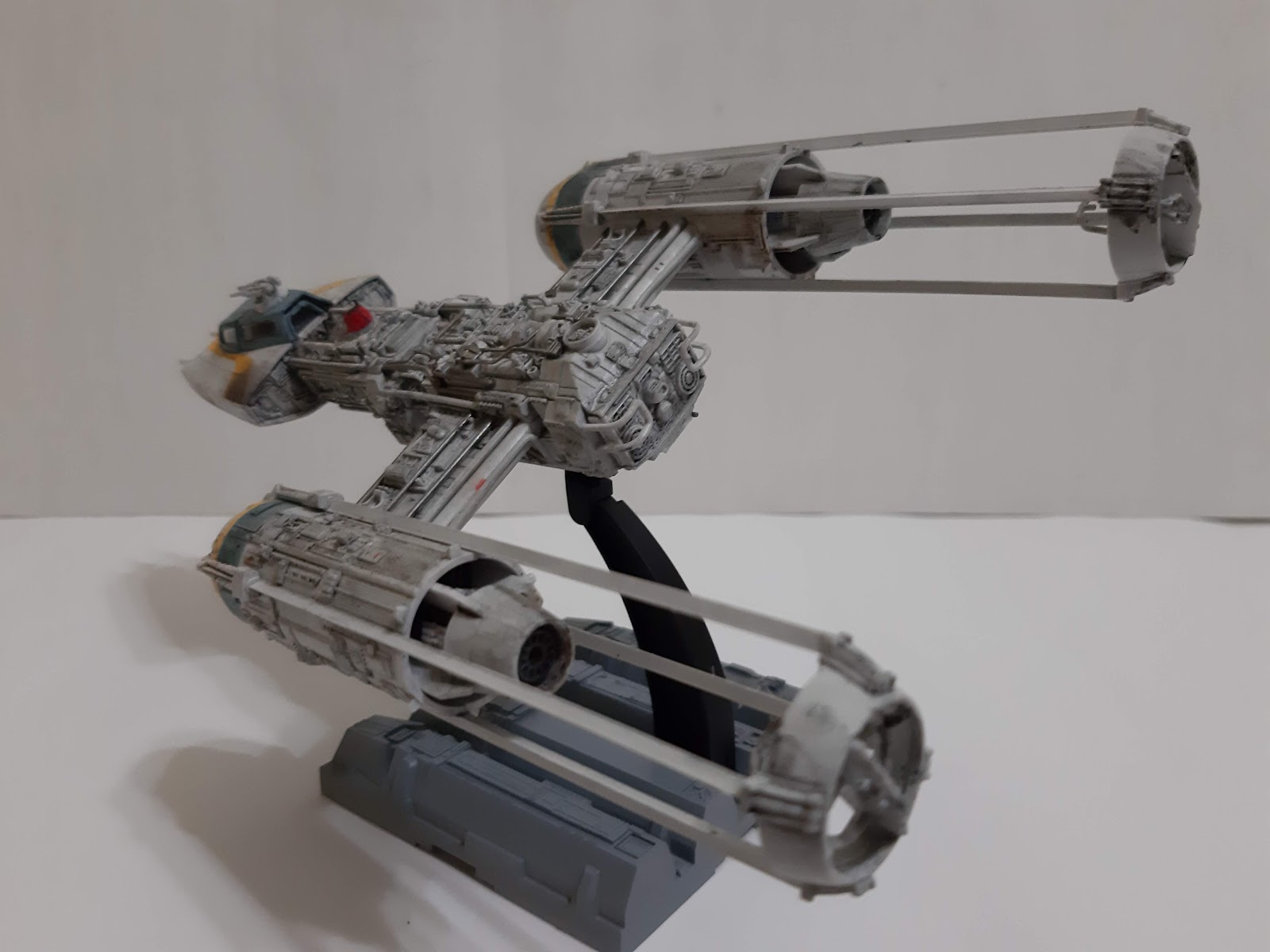
Koensayr Manufacturing BTL series of starfighters, better known as the 'Y-Wing' can trace its origins to the early Clone Wars era. The Galactic Republic commissioned the type as a combination of fighter and long-range bomber to supplement the V-19 Torrent and Delta-7 starfighters. Acquired by Jedi Knight Anakin Skywalker in an unsanctioned mission to retrieve the still-prototype craft, the BTL-B was used in an attack on General Grievous' flagship, the Malevolence. The success of the attack by the Shadow Squadron prompted Koensayr to develop other variants of the craft, including BTL-S3 and BTL-A4. The original BTL-B established the shape of the series with two large ion jet engines with their characteristic nacelles. The engines were carried by a cross wing which connected to the cockpit module on a central spar. The BTLs have a tendency to run hot which necessitated a complex cooling system throughout the craft.

Although production has started, the end of the Clone Wars and the rise of the Galactic Empire stopped any further production as the new Imperial Navy shifted towards capital ship-based  space superiority doctrine. As Koensayr lost their government contracts, the surplus stock of BTLs were sold to local planetary defence units although Imperial intervention caused many units remain unsold, being repossessed or sent to the salvage yard. As the BTL-B models were scrapped first, this made the -A4 version being the most numerous of the fighter. These idle craft became the focus of the nascent Rebellion in order to arm themselves. BTL-A4s were either purchased, or most of the time, stolen from military surplus dealers and scrapyards. Soon, the so-called Y-Wing fighter became the most common craft in the Rebel arsenal.

As mentioned before, the BTL-A4 is the single-seat version of the BTL-B with the second crewmember replaced with an astromech droid. For power, the craft had a Novaldex power generator and Thiodyne 03-R cryogenic power cells. Two Koensayr R200 ion jet engines were attached to either side of a central spar. At the front end of each engine nacelles were domes which contain  Fabritech  ANx-y long-range sensor arrays, PA-9r long-range phased tachyon detection array and PG-7u short-range primary threat analysis grid. Hyperspace capacity was provided by a R300-H hyperdrive mounted at the rear of the spar.  Armament comprised of a pair of forward-mounted Taim & Bak IX4 laser cannons, a pair of Arakyd Flex Tube proton torpedo launchers (with a payload of 8 Krupx GR7 proton torpedoes, or concussion missiles, ion torpedoes or proton bombs) and a pair of  turret-mounted ArMek SW-4 or SW-5 ion cannons (as the BTL-A4 is a single seat craft, the cannon was usually fixed to fire forward or towards the rear). While factory-fresh Y-Wings featured armour plating around the engines the central spar, Rebel technicians stripped them off to ease maintenance.

As the Alliance's workhorse starfighter, the Y-Wing was involved in numerous minor and major engagements during the Galactic Civil War including the Battle of Scarif, Battle of Yavin, Battle of Endor and Battle of Jakku.
-----------------------------------------------------------

The Y-Wing design is based on a concept art by Ralph MacQuarrie. As with the X-Wing design, the attack fighter was given the name 'Y-Wing' due to its resemblance to the capital letter Y when viewed from above. The fighter's rough appearance was the vision of Joe Johnston who envisioned that the factory-spec fighters were chopped and stripped like a hot rod by Rebel technicians.

The Kit
Bandai has been busy releasing kits of the Star Wars franchise vehicles and characters since acquiring the Star Wars licence from Disney.While I was quite skeptical before, all of the feelings were unfounded after building a number of their kits. The Y-Wing was released in 2015 and it featured all the hallmark of Bandai, including the multi-coloured sprue. The kit, as with most other Bandai Star Wars (or any other kit produced by them) is snap-fit but without the problems of old-style models of the same style of assembly. The raised details look very good and would benefit from washing process. As before, there are two types of canopies - one frames only without the glazing while the other is moulded in clear plastic. The latter can also be posed open. There were three pilot figures - one standing, the other two seated (one in the flight suit featured in Episode IV, the other in a suit featured in Episode VI). Two droids, an R2 and an R4 unit were also included. Markings were provided in decal and sticker form.

Construction
As usual with things that fly models, be it real or fictional, construction started at the pilot's 'office'. Although already moulded in black plastic, I painted it Vallejo Anthracite Gray as it looks more in-scale. The instrument and side panels can be painted as there are raised details. Alternatively, stickers or waterslide decals can be used after removing the said details. Too lazy to either paint or sand, I just apply the decals on the raised details. They however respond quite well to decal softening solution and that about covers it. The cannon barrels and the inside face of the coaming covering the barrel root were also painted before assembly. It should also be noted that the yellow trim seen on these ships in the movie was painted-on markings. Bandai however supplied them as a separate plastic piece, resulting in unnecessary panel line around it. The rear panel of the cockpit module include the rear cockpit transparency. This however is of the glazing-less type - fine if you want to use the frames-only canopy.

Construction then moved to the main fuselage. The moulding for this area is very nice and captures that rough, expeditionary feel of the original studio models. Also as a note of interest, the rear panel of the rear fuselage is a miniature of a Panther engine deck as used on the original studio model.The parts fit nicely with certain smaller parts need to be fitted to a larger part before being attached to the main body. Some parts didn't have positive 'snap-fitness' so I cemented them. The body of the astromech droid was painted but I didn't add any detail painting on it as it would be invisible inside the droid socket. I also didn't add most of the pipings seen on the surface of the rear fuselage as I think it would be better for me to add them after the fuselage has been painted.Also, due to some mis-handlings, the rail guards at the rear fuselage were bent. Anyway, just some gentle coaxing straightened them back.

Next up are the engine nacelles. Again the black-moulded parts were painted beforehand, this time with Burnt Iron. The nacelles are of multi-part assembly and some study of the assembly guide is needed to avoid mistakes. I painted the strip behind the sensor domes USAF Blue Grey (FS 32537) before adding the long, thin booms. As adding the thrust vanes at the end of the boom involved some fiddly handling, they were cemented (the glue, apart from securing the vane to the boom, also allow some friction allowing easier handling, at least to me!). Parts A5, A10 and B23 which are the landing gear doors, were also cemented as they did not securely fit into their slots plus I usually have my Star Wars models in flying pose. A piece of clear acetate was cut to shape and stuck to rear cockpit glazing while the central section of the canopy had the tab (to allow  it to be posed open) was cut. With that, the model is off to the paint shop.    . 

Painting and Decalling
Bandai's painting instructions are pretty generic and did not specify any particular brand. Browsing the internet, I came to the conclusion that USAF Light Gray (FS 36495) is the best colour. I used Vallejo 71.276 but added some variations. The exposed fuselage and the engine were painted 'neat' while the forward compartment and the sensor domes have the light gray added with white. I then checked with my Star Wars reference books on the colours of the pipings. The Star Wars Archive shows that the models used in filming have the same colour as the fuselage while the drawings in Star Wars Vehicles show them to be of a different colour. Diverging from erm, 'Canon' into 'Legends' the pipings were painted differently - some FS 36495, while others in Gunze Iron 2 and a mix of Gunze Brass and Silver.  The canopy frames were painted the Tamiya mix for US  BLUe Gray but somehow they were too dark for my liking - I lightened it up further with more Flat White. The few decals present were then applied as per the usual method. I intended the Y-Wing to be a rather generic Gold Squadron craft that took part in the Battles of Yavin and Scarif as depicted in the movies. So, the rather distinctive 'burn marks' were not added, just some 'carbon deposits' using Tamiya Weathering Master 'Soot'..

Finishing
I started by adding the engine nacelles to the rear fuselage. Again, no gluing is necessary here. Afterwards, the pipings for the rear fuselage were added. They mostly went in without problem but some locating holes were apparently too small requiring a bit of surgery either to the hole or the rod. There are quite a lot of them and I took several sessions to finish them ( I am a bit slower of late!). The work went slower when one of them broke and had to be repaired. The pilot figure was painted and then placed inside the cockpit. Since it was added after the cockpit had been completed, it was nearly impossible to fit his legs and so the legs were amputated at shin level. It also needed to be cemented to the seat as there are no tab-and-locating hole as with other the other kits. The canopy was put in place and I found that there is a gap between the rearmost canopy panel and the rear transparency. The model then received a wash with heavier application being done on the rear fuselage and the engine modules.  For the astromech droid, I  chose the R5 to add a bit more splash of colour. The whole model was then sprayed with Mr. Hobby Topcoat Flat Clear to finish. 

Conclusion
The geek in me continue to be awed by the range of Star Wars kits from Bandai. The details are well done while the construction is quite a snap (pun intended). My only comment with the kit was the rather disappointing fit of the pipings but the again, it might be just me. Anyway, building it was a breeze and allowed me to have a peace of mind before heading back into building another 500+ parts kit . Oh I forgot to mention about the turbolaser turret included in the A-Wing kit. It remain unbuild as I intended to display it together with the Y-Wing and an upcoming T-65 X-Wing fighter.  


Sunday, 5 January 2020

Easy Eight


Historical Background
The US Army followed the events in Europe 1939-1940 and decided that their current medium tank the M2, was obsolete to face contemporary battlefield challenges and designed the M3 Medium Tank (later nicknamed Lee/Grant). The M3 was a stop-gap measure, with the main 75 mm gun in a right-side sponson with limited field of fire. In late August 1940, the Ordnance Department submitted characteristics for a new design to replace the M3. Development of the prototype was delayed to allow the M3 design to be finished and enter production. On 18 April 1941, the Ordnance Department chose the simplest design, called the T6. It was basically a modified M3 hull and chassis and mounted a fully-rotating turret armed with the M3 75 mm gun. The design borrowed many features from existing tank design such as the vertical volute spring suspension, rubberised track links and the usage of Continental R975 radial engine. The T6 prototype was completed on 2 September 1941 and production commenced in the next month.

The production M4s were kept as close as possible to the M3, including the tracks, suspension and transmission. The hull upper hull however was changed to cast type and the side entry door was eliminated. The lower hull was made of large welded parts with the bogies bolted to the hull to ease maintenance and repair. The upper hull was cast for the M4A1 version and welded for the rest of the variants (plus the cast front and welded rear 'composite hull' M4). The M4 was powered by a Continental R975 air-cooled radial petrol engine rated at 400 hp. 660 liters of petrol was carried, allowing a range of 195 km. Later versions was powered by Ford V8 petrol or General Motors diesel engine. The frontal armour was 51 mm thick while the turret front was between 64 mm to 76 mm, The front upper hull was angled at 56 degrees with the lower half rounded, making the armour effective against most early war anti-tank weapons. Even so, the early versions had shot traps, located just in front of the driver and co-driver's positions.

The M4, nicknamed Sherman (after General William Tecumseh Sherman) was originally armed with a L/40 M3 75 mm gun. The standard M61 round fired by this gun can penetrate 87 mm of RHA at 100 meters and 70 mm at 1,000 meters, sufficient to destroy Panzer IIIs and IVs. After protracted development, the Sherman was later armed with a more powerful M1/M1A2 76 mm gun, in a new T23 turret, giving it at least a parity with L/48-armed Panzer IVs. The main armament was backed by two Browning M1919 machine guns; one co-axial with  with the main gun and another in the hull. 60 rounds was provided for the main gun with the machine guns shared 4,750 rounds between them. For anti-aircraft and further anti-infantry/soft-skin capability, a Browning M2 12.7 mm machine gun can be mounted on the roof.  The Sherman was manned by a crew of five: commander, gunner, loader, driver and assistant driver/hull gunner. Each of the crew members had a periscope to allow 360-degree view of the outside.

Production began at the Lima Locomotive Works, Lima, Ohio with all the first production tanks going to the British Army. By the end of the war, ten other production lines were opened, delivering some 48,000 M4s. The Sherman was produced in a  number of variants but the most produced ,a nd the preferred model by the US Army was the M4A3. The M4A3 was basically the same with the M4 but was powered by a Ford GAA V-8 engine. The early M4A3s were armed with a shorter (L/31) M2 75 mm gun, which was later replaced with the L/40 M3 gun. Late versions of the M4A3 was armed with the more powerful M1/M1A1 76 mm gun. Work was also done to improve the Sherman's ride qualities and  this resulted in the finalization of the Horizontal Volute-Spring Suspension or HVSS.  Wider track was also included with the HVSS system. While this resulted in a heavier and wider vehicle, the ground pressure is reduced. The HVSS was applied to the late M4A3 variant and resulted in the M4A3(76)W HVSS or M4A3E8. The latter designation, coupled with the easier ride of the HVSS gave rise to the 'Easy Eight' nickname for this variant. A total of 2,617 M4A3E8 were built between by Detroit Tank Arsenal between August 1944 and April 1944.

The Sherman was originally issued in small numbers to familiarise the US Armored Divisions. American Shermans saw their first combat during Operation Torch in November 1942. The M4A1 (and the original M4) were the prime variants used by the US Army until the introduction of the M4A3 with a more powerful (500 hp) engine. The Easy Eight saw their first action during The Battle Of The Bulge. As individual tanks, the Sherman was inferior to the German tanks such as the Panther being weakly armed (at least for the early version) and thinly armoured. As a type however, it was superior to the German panzers, being reliable, easy to maintain and more mobile than the ponderous Tigers. Easy Eight were retained by the US Army post-World War 2 and saw combat again during the Korean War.

The Kit
In the 1970s, Tamiya came up with their kit of the Easy Eight and it is suffice to say that it is a collector's item. Although Tamiya released a number of new mould 'mainstream' M4A3s in the late 90s and the early Noughties, the M4A3E8 remain unkitted by them. In 2014, they released the re-boxed Asuka kit and eventually, in 2015, they released their own kit of the Easy Eight. This kit is packed inside a rather small (for a 1/35 WW2-era medium tank kit) box. Opening up the box, there are just six olive-colored sprues, one clear sprue, lower hull, turret shell, a pair of band-style rubber tracks, decals, poly caps and the instruction sheet. Obviously many parts, especially the HVSS were simplified, but the existing details are sufficient for many modellers. The relevant parts also has convincing cast texture moulded. Being a Tamiya kit, I don't expect any complications during construction. The decal sheet markings for two Easy Eights (the difference between the two is that one of them sports a blacked-out Allied Star).

Construction
Instead of a single hull pan, Tamiya has the lower hull as a multi-part assembly. The left and right side pieces have a further sub-piece which need to be cemented first. The joint between the side pieces and the bottom piece is reinforced by part P2. Apparently the engine bulkhead, Tamiya moulded holes in it for the non-existant engine (although they may be useful for those who wants more details for their model). The rear hull panel were next. No problem here but Tamiya apparently forgot to include the engine access door in their instructions. The part is however easily identified on the sprue. Moving to the transmission cover, I lost Part L9 to the Carpet Monster and have to fashion a replacement (badly!) using scrap plastic. The exhaust deflectors were assembled but I couldn't orient them in place. I'm not sure myself, but I think that the position for R17 and R18 should be swapped (either that or I somehow got it wrong while trying to insert it in place!). In the end, I just cut off the tabs and glued the deflector in place.

As mentioned before, the HVSS suspension is one of the items simplified in the Tamiya kit. While this means no articulation and lesser details, it makes up for a quick and hassle-free build. The main suspension unit consists of just four parts per bogie (not including the wheels and the mount). They were quickly assembled but for a short while was set aside as I wanted to do some weathering on the lower hull. The tracks were painted beforehand using AK Interactive Track Primer, followed by the same company's Track Wash. The tracks were later drybrushed silver. The ends can be joined together using regular hobby cement but I stick to using cyanoarcyclate glue. The tracks for my kit is a bit warped at the ends but it was easily rectified by cement. They fit without problem and the orientat

The upper hull is designed so that it can be attached to the lower without cement. Tamiya did this by using a clip at the front and a large pin which slots into a poly cap arrangement at the rear. The hull sponson, which was hollow in previous Tamiya (in-house) Sherman kits is closed by the fenders. The latter is also made stable with a spacer. Holes for the lifting lugs at the front hull were the drilled. And just to get the repetitive out of the way, the fender braces were cemented first. Since I intended to have the crew hatches shut, the periscopes were left off. While the front lifting lugs were moulded 'whole', the rear pair were moulded in half, and were to be cemented to stubs on the rear deck. Most of the fittings on the upper hull were then cemented but I temporarily left the pioneer tools and spare track links off to ease painting. The rear hull rack, while assembled, was also left off at this time. The upper hull was then attached to the lower hull. I applied a bit of Tamiya Thin Cement to close the few tiny gaps along the joint.

Painting and Decalling
There is just one colour used for US World War 2 era vehicles. This time I used Vallejo Air 743 Olive Drab. I was thinking of adding a brown filter after the initial paint layer has dried but apparently (according to Tamiya), late-war OD have a more greenish hue than the OD used earlier. So I ditched the brown filter. Wash solution from AK Interactive was then used to visually raise the details. The tools were also painted while still on the sprue although I used sand yellow to paint the wooden handles. Once dried, brown wash was used to make them look more like wood. Afterwards, it was time for the decals. As mentioned before, the markings selection is very bland with just two anonymous Easy Eights from the 4th and the 5th Armoured Divisions. While the majority of M4A3E8s at the time were indeed devoid of personalised markings, I wonder why didn't Tamiya pick the ones with those markings. I tried to make it look more interesting by using markings from the 4th AD with the blacked out US stars on the turret. With just four pieces of decals, this process took less than 10 minutes! 

Finishing
I brown-washed a pair of wood piece and placed them on the front of the hull (the bracket of this purpose has already been moulded in place). The model then received the usual wash and I tried the streaking method for this model. The running gear and the tracks received a rather thick pasting of Vallejo Dark Mud. Parts where the muddy boots of the crew stepped on the tank were splattered with a light mud solution. Afterwards, tank supplies using parts from Academy, Tamiya, Hero and the stash were placed on the relevant parts of the model. To hang the stuff on the turret, I cemented a length of plastic rod on the right side of the turret. I then robbed the metal tow cable from my broken Dragon M4A3(76) and placed it on the model. The commander's machine gun and the gun cradle were replaced with spares from Dragon's Sherman Firefly The original kit's cradle was cut and replaced. Since the I chose the markings for a tank in Bastogne during the Battle Of The Bulge,, I think I wanted to add some 'snow'. Using a mixture of water and white glue as adhesive, I sprinkled (and also mixing it with the aforementioned adhesive) sodium bicarbonate on the tracks, road wheels and at various points on the model.

Conclusion
If you want to punish yourself build an intricate kit with all the bells, whistles and screws, this model is not for you. The Tamiya kit is geared towards the more casual crowd (or those seeking relief after building 1,000+ parts kits). Anyway, admittedly mre simplified than its rivals, the Tamiya kit of E8 does have sharp and nice enough details. The letdown in this kit (to my viewpoint) is the rather uninspired markings chosen. This was can however be an advantage: being rather nondescript, you can work to your heart's content with regards to additional items you want to add to the model.